- 您現在的位置:買賣IC網 > PDF目錄98220 > THS14F03CPFB (TEXAS INSTRUMENTS INC) 1-CH 14-BIT PROPRIETARY METHOD ADC, PARALLEL ACCESS, PQFP48 PDF資料下載
參數資料
| 型號: | THS14F03CPFB |
| 廠商: | TEXAS INSTRUMENTS INC |
| 元件分類: | ADC |
| 英文描述: | 1-CH 14-BIT PROPRIETARY METHOD ADC, PARALLEL ACCESS, PQFP48 |
| 封裝: | PLASTIC, TQFP-48 |
| 文件頁數: | 18/24頁 |
| 文件大小: | 329K |
| 代理商: | THS14F03CPFB |
THS14F01, THS14F03
14-BIT, 1 MSPS/ 3 MSPS, DSP COMPATIBLE, ANALOG-TO-DIGITAL CONVERTERS
WITH FIFO INTERNAL REFERENCE AND PGA
SLAS285 – JUNE 2000
3
POST OFFICE BOX 655303
DALLAS, TEXAS 75265
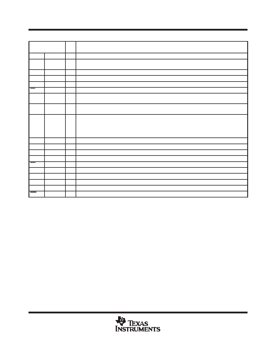
Terminal Functions
TERMINAL
I/O
DESCRIPTION
NAME
NO.
I/O
DESCRIPTION
A[1:0]
40, 41
I
Address input
AGND
7,8, 44,
45, 46
P
Analog ground
AVDD
2, 43, 47
P
Analog power supply
CLK
32
I
Clock input
CML
4
Reference midpoint. This pin requires a 0.1-
F capacitor to AGND.
CS
37
I
Chip select input. Active low
DGND
9, 15, 25,
33, 34
P
Digital ground
DVDD
14, 20, 26,
30, 31, 42
P
Digital power supply
D[13:0]
11, 12, 13,
16, 17, 18,
19, 21, 22,
23, 24, 27,
28, 29
I/O
Data inputs/outputs
FOVL
39
O
FIFO Overflow. Asserted when FIFO is full. Programmable polarity
IN+
48
I
Positive differential analog input
IN–
1
I
Negative differential analog input
INT
38
O
Interrupt output. Asserted when FIFO trigger level is reached. Programmable polarity
OE
35
I
Output enable. Active low
OV
10
O
Out of range output
REF+
5
O
Positive reference output. This pin requires a 0.1-
F capacitor to AGND.
REF–
6
O
Negative reference output. This pin requires a 0.1-
F capacitor to AGND.
VBG
3
I
Reference input. This pin requires a 1-
F capacitor to AGND.
WR
36
I
Write signal. Active low
absolute maximum ratings over operating free-air temperature (unless otherwise noted)
Supply voltage, (AVDD to AGND)
4V
. . . . . . . . . . . . . . . . . . . . . . . . . . . . . . . . . . . . . . . . . . . . . . . . . . . . . . . . . . . . .
Supply voltage, (DVDD to DGND)
4V
. . . . . . . . . . . . . . . . . . . . . . . . . . . . . . . . . . . . . . . . . . . . . . . . . . . . . . . . . . . . .
Reference input voltage range, VBG
– 0.3 V to AVDD + 0.3 V
. . . . . . . . . . . . . . . . . . . . . . . . . . . . . . . . . . . . . . .
Analog input voltage range
– 0.3 V to AVDD + 0.3 V
. . . . . . . . . . . . . . . . . . . . . . . . . . . . . . . . . . . . . . . . . . . . . . . . .
Digital input voltage range
– 0.3 V to DVDD + 0.3 V
. . . . . . . . . . . . . . . . . . . . . . . . . . . . . . . . . . . . . . . . . . . . . . . . .
Operating free-air temperature range, TA: C suffix
0
°C to 70°C
. . . . . . . . . . . . . . . . . . . . . . . . . . . . . . . . . . . . . .
I suffix
–40
°C to 85°C
. . . . . . . . . . . . . . . . . . . . . . . . . . . . . . . . . . . . .
Storage temperature range, Tstg
–65
°C to 150°C
. . . . . . . . . . . . . . . . . . . . . . . . . . . . . . . . . . . . . . . . . . . . . . . . . .
Lead temperature 1.6 mm (1/16 inch) from case for 10 seconds
260
°C
. . . . . . . . . . . . . . . . . . . . . . . . . . . . . . . .
Stresses beyond those listed under “absolute maximum ratings” may cause permanent damage to the device. These are stress ratings only, and
functional operation of the device at these or any other conditions beyond those indicated under “recommended operating conditions” is not
implied. Exposure to absolute-maximum-rated conditions for extended periods may affect device reliability.
相關PDF資料 |
PDF描述 |
|---|---|
| THS14F03IPFBG4 | 1-CH 14-BIT PROPRIETARY METHOD ADC, PARALLEL ACCESS, PQFP48 |
| THS14F03IPFB | 1-CH 14-BIT PROPRIETARY METHOD ADC, PARALLEL ACCESS, PQFP48 |
| THS14F01IPFBG4 | 1-CH 14-BIT PROPRIETARY METHOD ADC, PARALLEL ACCESS, PQFP48 |
| THS3001CDGNRG4 | 1 CHANNEL, VIDEO AMPLIFIER, PDSO8 |
| THS3001HVCDGN | 1 CHANNEL, VIDEO AMPLIFIER, PDSO8 |
相關代理商/技術參數 |
參數描述 |
|---|---|
| THS14F03EVM | 功能描述:數據轉換 IC 開發工具 THS14F03 Eval Mod RoHS:否 制造商:Texas Instruments 產品:Demonstration Kits 類型:ADC 工具用于評估:ADS130E08 接口類型:SPI 工作電源電壓:- 6 V to + 6 V |
| THS14F03IPFB | 功能描述:模數轉換器 - ADC 14-bit 3 MSPS with 32-word FIFO RoHS:否 制造商:Texas Instruments 通道數量:2 結構:Sigma-Delta 轉換速率:125 SPs to 8 KSPs 分辨率:24 bit 輸入類型:Differential 信噪比:107 dB 接口類型:SPI 工作電源電壓:1.7 V to 3.6 V, 2.7 V to 5.25 V 最大工作溫度:+ 85 C 安裝風格:SMD/SMT 封裝 / 箱體:VQFN-32 |
| THS14F03IPFBG4 | 功能描述:模數轉換器 - ADC 14-bit 3 MSPS with 32-word FIFO RoHS:否 制造商:Texas Instruments 通道數量:2 結構:Sigma-Delta 轉換速率:125 SPs to 8 KSPs 分辨率:24 bit 輸入類型:Differential 信噪比:107 dB 接口類型:SPI 工作電源電壓:1.7 V to 3.6 V, 2.7 V to 5.25 V 最大工作溫度:+ 85 C 安裝風格:SMD/SMT 封裝 / 箱體:VQFN-32 |
| THS14-THS18-D | 制造商:Thomas & Betts 功能描述:CATAMOUNT CABLE TIES |
| THS15 | 制造商:未知廠家 制造商全稱:未知廠家 功能描述:EURO TERMINAL BLOCKS |
發布緊急采購,3分鐘左右您將得到回復。