- 您現在的位置:買賣IC網 > PDF目錄98254 > TLV320AIC3110IRHBT (TEXAS INSTRUMENTS INC) AUDIO AMPLIFIER, PQCC32 PDF資料下載
參數資料
| 型號: | TLV320AIC3110IRHBT |
| 廠商: | TEXAS INSTRUMENTS INC |
| 元件分類: | 音頻/視頻放大 |
| 英文描述: | AUDIO AMPLIFIER, PQCC32 |
| 封裝: | 5 X 5 MM, GREEN, PLASTIC, QFN-32 |
| 文件頁數: | 117/126頁 |
| 文件大小: | 1528K |
| 代理商: | TLV320AIC3110IRHBT |
第1頁第2頁第3頁第4頁第5頁第6頁第7頁第8頁第9頁第10頁第11頁第12頁第13頁第14頁第15頁第16頁第17頁第18頁第19頁第20頁第21頁第22頁第23頁第24頁第25頁第26頁第27頁第28頁第29頁第30頁第31頁第32頁第33頁第34頁第35頁第36頁第37頁第38頁第39頁第40頁第41頁第42頁第43頁第44頁第45頁第46頁第47頁第48頁第49頁第50頁第51頁第52頁第53頁第54頁第55頁第56頁第57頁第58頁第59頁第60頁第61頁第62頁第63頁第64頁第65頁第66頁第67頁第68頁第69頁第70頁第71頁第72頁第73頁第74頁第75頁第76頁第77頁第78頁第79頁第80頁第81頁第82頁第83頁第84頁第85頁第86頁第87頁第88頁第89頁第90頁第91頁第92頁第93頁第94頁第95頁第96頁第97頁第98頁第99頁第100頁第101頁第102頁第103頁第104頁第105頁第106頁第107頁第108頁第109頁第110頁第111頁第112頁第113頁第114頁第115頁第116頁當前第117頁第118頁第119頁第120頁第121頁第122頁第123頁第124頁第125頁第126頁
SLAS647 – DECEMBER 2009
www.ti.com
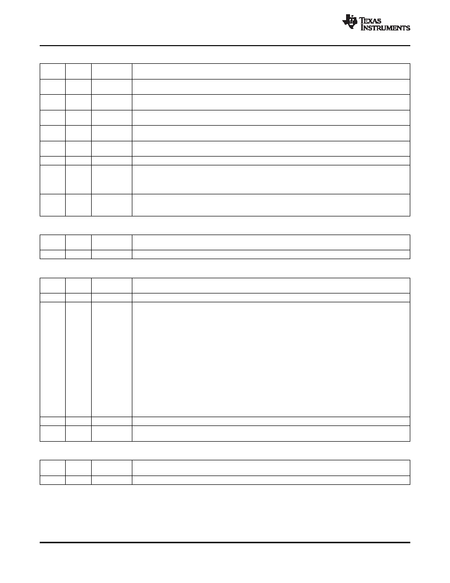
Page 0 / Register 49 (0x31): INT2 Control Register
READ/
RESET
BIT
DESCRIPTION
WRITE
VALUE
D7
R/W
0
0: Headset-insertion detect interrupt is not used in the generation of INT2 interrupt.
1: Headset-insertion detect interrupt is used in the generation of INT2 interrupt.
D6
R/W
0
0: Button-press detect interrupt is not used in the generation of INT2 interrupt.
1: Button-press detect interrupt is used in the generation of INT2 interrupt.
D5
R/W
0
0: DAC DRC signal-power interrupt is not used in the generation of INT2 interrupt.
1: DAC DRC signal-power interrupt is used in the generation of INT2 interrupt.
D4
R/W
0
0: ADC AGC noise interrupt is not used in the generation of INT2 interrupt.
1: ADC AGC noise interrupt is used in the generation of INT2 interrupt.
D3
R/W
0
0: Short-circuit interrupt is not used in the generation of INT2 interrupt.
1: Short-circuit interrupt is used in the generation of INT2 interrupt.
D2
R
0
Reserved. Write only zero.
D1
R/W
0
0: DC measurement using the audio ADC data-available interrupt is not used in the generation of INT2
interrupt
1: DC measurement using the audio ADC data-available interrupt is used in the generation of INT2
interrupt
D0
R/W
0
0: INT2 is only one pulse (active-high) of typical 2-ms duration.
1: INT2 is multiple pulses (active-high) of typical 2-ms duration and 4-ms period, until flag registers 44
and 45 are read by the user.
Page 0 / Register 50 (0x32): Reserved
READ/
RESET
BIT
DESCRIPTION
WRITE
VALUE
D7-D0
R/W
0000 0000
Reserved. Write only reset values.
Page 0 / Register 51 (0x33): GPIO1 In/Out Pin Control
READ/
RESET
BIT
DESCRIPTION
WRITE
VALUE
D7–D6
R/W
XX
Reserved. Do not write any value other than reset value.
D5–D2
R/W
0000
0000: GPIO1 disabled (input and output buffers powered down)
0001: GPIO1 is in input mode (can be used as secondary BCLK input, secondary WCLK input,
secondary DIN input, ADC_WCLK input, Dig_Mic_In or in ClockGen block).
0010: GPIO1 is used as general-purpose input (GPI).
0011: GPIO1 output = general-purpose output
0100: GPIO1 output = CLKOUT output
0101: GPIO1 output = INT1 output
0110: GPIO1 output = INT2 output
0111: GPIO1 output = ADC_WCLK output for codec interface
1000: GPIO1 output = secondary BCLK output for codec interface
1001: GPIO1 output = secondary WCLK output for codec interface
1010: GPIO1 output = ADC_MOD_CLK output for the digital microphone
1011: GPIO1 output = secondary DOUT for codec interface
1100: Reserved
1101: Reserved
1110: Reserved
1111: Reserved
D1
R
X
GPIO1 input buffer value
D0
R/W
0
0: GPIO1 general-purpose output value = 0
1: GPIO1 general-purpose output value = 1
Page 0 / Register 52 (0x34): Reserved
READ/
RESET
BIT
DESCRIPTION
WRITE
VALUE
D7–D0
R/W
XXXX XXXX
Reserved. Do not write any value other than reset value.
90
REGISTER MAP
Copyright 2009, Texas Instruments Incorporated
Product Folder Link(s): TLV320AIC3110
相關PDF資料 |
PDF描述 |
|---|---|
| TLV320AIC3111IRHBT | AUDIO AMPLIFIER, PQCC32 |
| TLV320AIC3111IRHBR | AUDIO AMPLIFIER, PQCC32 |
| TLV320AIC3120IRHBR | AUDIO AMPLIFIER, PQCC32 |
| TLV320AIC3120IRHBT | AUDIO AMPLIFIER, PQCC32 |
| TLV320AIC31IRHBRG4 | SPECIALTY CONSUMER CIRCUIT, PQCC32 |
相關代理商/技術參數 |
參數描述 |
|---|---|
| TLV320AIC3111 | 制造商:TI 制造商全稱:Texas Instruments 功能描述:Low-Power Audio Codec With Embedded miniDSP and Stereo Class-D Speaker Amplifier |
| TLV320AIC3111_101 | 制造商:TI 制造商全稱:Texas Instruments 功能描述:Low-Power Audio Codec With Embedded miniDSP and Stereo Class-D Speaker Amplifier |
| TLV320AIC3111EVM-K | 功能描述:音頻 IC 開發工具 TLV320AIC3111 Eval Mod RoHS:否 制造商:Texas Instruments 產品:Evaluation Kits 類型:Audio Amplifiers 工具用于評估:TAS5614L 工作電源電壓:12 V to 38 V |
| TLV320AIC3111IRHBR | 功能描述:接口—CODEC Low-Pwr Audio CODEC RoHS:否 制造商:Texas Instruments 類型: 分辨率: 轉換速率:48 kSPs 接口類型:I2C ADC 數量:2 DAC 數量:4 工作電源電壓:1.8 V, 2.1 V, 2.3 V to 5.5 V 最大工作溫度:+ 85 C 安裝風格:SMD/SMT 封裝 / 箱體:DSBGA-81 封裝:Reel |
| TLV320AIC3111IRHBT | 功能描述:接口—CODEC Low-Pwr Audio CODEC RoHS:否 制造商:Texas Instruments 類型: 分辨率: 轉換速率:48 kSPs 接口類型:I2C ADC 數量:2 DAC 數量:4 工作電源電壓:1.8 V, 2.1 V, 2.3 V to 5.5 V 最大工作溫度:+ 85 C 安裝風格:SMD/SMT 封裝 / 箱體:DSBGA-81 封裝:Reel |
發布緊急采購,3分鐘左右您將得到回復。