- 您現在的位置:買賣IC網 > PDF目錄98266 > TMC57750PM (TEXAS INSTRUMENTS INC) SPECIALTY CONSUMER CIRCUIT, PQFP64 PDF資料下載
參數資料
| 型號: | TMC57750PM |
| 廠商: | TEXAS INSTRUMENTS INC |
| 元件分類: | 消費家電 |
| 英文描述: | SPECIALTY CONSUMER CIRCUIT, PQFP64 |
| 封裝: | PLASTIC, LQFP-64 |
| 文件頁數: | 11/16頁 |
| 文件大小: | 257K |
| 代理商: | TMC57750PM |
TMC57750
1/4-INCH RS-170 TIMER
SOCS041 – JUNE 1994
4
POST OFFICE BOX 655303
DALLAS, TEXAS 75265
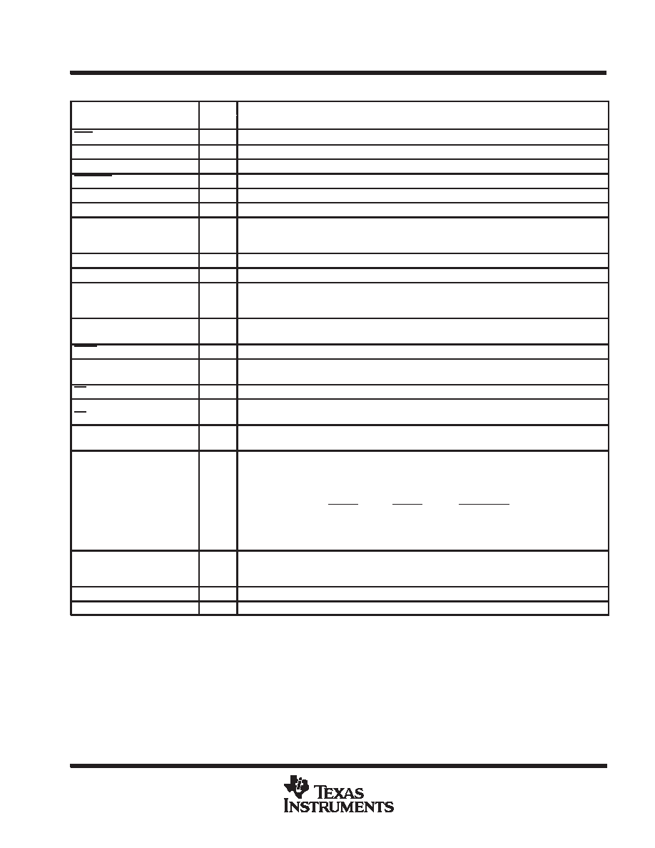
Terminal Functions (Continued)
TERMINAL
I/O
DESCRIPTION
NAME
NO.
I/O
DESCRIPTION
PUC
44
I
Power-up clear
SAG
56
O
Storage-area gate
SCAN
43
SCAN is a test point and is not used in normal operation.
SHTCOM
31
I
Shutter command
SRG
54
O
Serial-register gate
SRM
53
O
Serial-register gate mid-level
SRGSEL
49
I
Serial-register gate select. SRGSEL selects the readout frequency. When SRGSEL is high, the
standard frequency of 6.25 MHz is selected. When low, the double frequency of 12.5 MHz is
selected.
SHTMON
33
O
Shutter monitor
S/H
34
O
Sample and hold
SEL1,
SEL2,
SEL3
25, 27, 28
I
Shutter-speed select. SEL1, SEL2, and SEL3 selects the fixed shutter times in horizontal TV lines.
This selection sets the exposure times if either the manual-shutter or random-shutter modes are
selected (see Table 2).
TEST1, TEST2,
TEST3, TEST4
1, 2,
3, 19
TEST1, TEST2, TEST3, and TEST4 are test points and are not used in normal operation.
VACT
32
O
Video active
VCC
13, 26,
45, 59
Supply voltage
VD
47
O
Vertical drive
VR
29
I
Vertical reset
WINDOW
16
O
Window. WINDOW is high as defined by WSEL1 and WSEL2 at the times in TV lines and horizontal
pixels (see Table 3).
WSEL1,
WSEL2
14, 15
I
Window select. WSEL1 and WSEL2 selects the output mode of WINDOW. These inputs are
normally used with the auto-iris mode in selecting the desired region to optimize the exposure of
the best image (see Table 3).
WSEL1
WSEL2
OPERATION
H
MODE1
L
H
MODE2
H
L
MODE3
L
MODE4
XSEL
39
I
Crystal-oscillator select. XSEL selects the inputs used as the master clock. When XSEL is high, a
25-MHz crystal is connected between XIN and XOUT. When XSEL is low, a 25-MHz crystal
oscillator is required and its output connected to CLKIN.
XIN
41
Crystal in
XOUT
40
Crystal out
absolute maximum ratings over operating free-air temperature range (unless otherwise noted)
Supply voltage range, VCC
– 0.5 V to 6 V
. . . . . . . . . . . . . . . . . . . . . . . . . . . . . . . . . . . . . . . . . . . . . . . . . . . . . . . . . .
Input voltage range, VI
– 0.5 V to VCC + 0.5 V
. . . . . . . . . . . . . . . . . . . . . . . . . . . . . . . . . . . . . . . . . . . . . . . . . . . . . .
Output voltage range, VO
– 0.5 V to VCC + 0.5 V
. . . . . . . . . . . . . . . . . . . . . . . . . . . . . . . . . . . . . . . . . . . . . . . . . . .
Operating free-air temperature range, TA
–20
°C to 45°C
. . . . . . . . . . . . . . . . . . . . . . . . . . . . . . . . . . . . . . . . . . . .
Storage temperature range, TSTG
–65
°C to 150°C
. . . . . . . . . . . . . . . . . . . . . . . . . . . . . . . . . . . . . . . . . . . . . . . . .
Lead temperature 1,6 mm (1/16 inch) from case for 10 seconds
260
°C
. . . . . . . . . . . . . . . . . . . . . . . . . . . . . . .
相關PDF資料 |
PDF描述 |
|---|---|
| TMC57750 | SPECIALTY CONSUMER CIRCUIT, PQFP64 |
| TMDS250PAGRG4 | SPECIALTY CONSUMER CIRCUIT, PQFP64 |
| TMDS250PAGR | SPECIALTY CONSUMER CIRCUIT, PQFP64 |
| TMDS251PAGR | 3-CHANNEL, AUDIO/VIDEO SWITCH, PQFP64 |
| TMDS251PAGRG4 | 3-CHANNEL, AUDIO/VIDEO SWITCH, PQFP64 |
相關代理商/技術參數 |
參數描述 |
|---|---|
| TMC-5A31 | 制造商:未知廠家 制造商全稱:未知廠家 功能描述:High Speed VCSEL TO-46 metal can |
| TMC-5A31-801 | 制造商:未知廠家 制造商全稱:未知廠家 功能描述:High Speed VCSEL TO-46 metal can |
| TMC-5A31-802 | 制造商:未知廠家 制造商全稱:未知廠家 功能描述:High Speed VCSEL TO-46 metal can |
| TMC-5A31-803 | 制造商:未知廠家 制造商全稱:未知廠家 功能描述:High Speed VCSEL TO-46 metal can |
| TMC-5A31-XXX | 制造商:未知廠家 制造商全稱:未知廠家 功能描述:High Speed VCSEL TO-46 metal can |
發布緊急采購,3分鐘左右您將得到回復。