- 您現(xiàn)在的位置:買賣IC網(wǎng) > PDF目錄382662 > TOP232Y Analog IC PDF資料下載
參數(shù)資料
| 型號(hào): | TOP232Y |
| 英文描述: | Analog IC |
| 中文描述: | 模擬IC |
| 文件頁數(shù): | 5/36頁 |
| 文件大小: | 650K |
| 代理商: | TOP232Y |
第1頁第2頁第3頁第4頁當(dāng)前第5頁第6頁第7頁第8頁第9頁第10頁第11頁第12頁第13頁第14頁第15頁第16頁第17頁第18頁第19頁第20頁第21頁第22頁第23頁第24頁第25頁第26頁第27頁第28頁第29頁第30頁第31頁第32頁第33頁第34頁第35頁第36頁
TOP232-234
B
7/01
5
PI-2545-082299
S1
S2
~
S6
S7
S1
S2
~
S6
S7
S0
S1
S7
S0
S0
5.8 V
4.8 V
S7
0 V
0 V
0 V
V
LINE
V
C
V
DRAIN
V
OUT
0 V
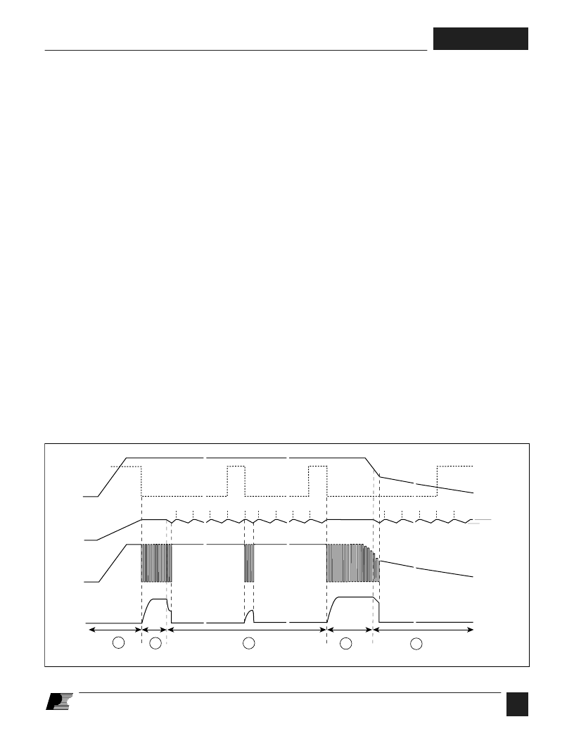
Note: S0 through S7 are the output states of the auto-restart counter
2
1
2
3
4
~
~
~
~
S6
S7
~
~
~
~
V
UV
~
~
~
~
S2
~
CONTROL pin current, before the CONTROL pin voltage has
had a chance to discharge to the lower threshold voltage of
approximately 4.8 V (internal supply under-voltage lockout
threshold). When the externally fed current charges the
CONTROL pin to the shunt regulator voltage of 5.8 V, current
in excess of the consumption of the chip is shunted to SOURCE
through resistor R
as shown in Figure 2. This current flowing
through R
controls the duty cycle of the power MOSFET to
provide closed loop regulation. The shunt regulator has a finite
low output impedance Z
that sets the gain of the error amplifier
when used in a primary feedback configuration. The dynamic
impedance Z
of the CONTROL pin together with the external
CONTROL pin capacitance sets the dominant pole for the
control loop.
When a fault condition such as an open loop or shorted output
prevents the flow of an external current into the CONTROL pin,
the capacitor on the CONTROL pin discharges towards 4.8 V.
At 4.8 V auto-restart is activated which turns the output MOSFET
off and puts the control circuitry in a low current standby mode.
The high-voltage current source turns on and charges the
external capacitance again. A hysteretic internal supply under-
voltage comparator keeps V
within a window of typically 4.8
to 5.8 V by turning the high-voltage current source on and off
as shown in Figure 5. The auto-restart circuit has a divide-by-
8 counter which prevents the output MOSFET from turning on
again until eight discharge/charge cycles have elapsed. This is
accomplished by enabling the output MOSFET only when the
divide-by-8 counter reaches full count (S7). The counter
effectively limits
TOPSwitch-FX
power dissipation by reducing
the auto-restart duty cycle to typically 4%. Auto-restart mode
continues until output voltage regulation is again achieved
through closure of the feedback loop.
Oscillator and Switching Frequency
The internal oscillator linearly charges and discharges an internal
capacitance between two voltage levels to create a sawtooth
waveform for the pulse width modulator. The oscillator sets the
pulse width modulator/current limit latch at the beginning of
each cycle.
The nominal switching frequency of 132 kHz was chosen to
minimize transformer size while keeping the fundamental EMI
frequency below 150 kHz. The FREQUENCY pin (available
only in TO-220 package), when shorted to the CONTROL pin,
lowers the switching frequency to 66 kHz (half frequency)
which may be preferable in some cases such as noise sensitive
video applications or a high efficiency standby mode. Otherwise,
the FREQUENCY pin should be connected to the SOURCE pin
for the default 132 kHz. Trimming of the current reference
improves oscillator frequency accuracy.
To further reduce the EMI level, the switching frequency is
jittered (frequency modulated) by approximately
±
4 kHz at
250 Hz (typical) rate as shown in Figure 6. Figure 28 shows the
typical improvement of EMI measurements with frequency
jitter.
Pulse Width Modulator and Maximum Duty Cycle
The pulse width modulator implements voltage mode control
by driving the output MOSFET with a duty cycle inversely
proportional to the current into the CONTROL pin
that is in
excess of the internal supply current of the chip (see Figure 4).
The excess current is the feedback error signal that appears
across R
(see Figure 2). This signal is filtered by an RC
network with a typical corner frequency of 7 kHz to reduce the
effect of switching noise in the chip supply current generated by
Figure 5. Typical Waveforms for (1) Power Up (2) Normal Operation (3) Auto-restart (4) Power Down .
相關(guān)PDF資料 |
PDF描述 |
|---|---|
| TOP233G | Analog IC |
| TOP232-234 | Family Design Flexible,EcoSmart, Intergrated OFff-line Switcher |
| TOP242F | SMPS Controller |
| TOP242G-TL | SMPS Controller |
| TOP242R-TL | SMPS Controller |
相關(guān)代理商/技術(shù)參數(shù) |
參數(shù)描述 |
|---|---|
| TOP232YN | 功能描述:交流/直流開關(guān)轉(zhuǎn)換器 15W 85-265 VAC 25W 230 VAC RoHS:否 制造商:STMicroelectronics 輸出電壓:800 V 輸入/電源電壓(最大值):23.5 V 輸入/電源電壓(最小值):11.5 V 開關(guān)頻率:115 kHz 電源電流:1.6 mA 工作溫度范圍:- 40 C to + 150 C 安裝風(fēng)格:SMD/SMT 封裝 / 箱體:SSO-10 封裝:Reel |
| TOP233 | 制造商:未知廠家 制造商全稱:未知廠家 功能描述:TOPSwifch® -FX 系列采用EcoSmart®節(jié)能技術(shù)的離線式集成開關(guān)電源 |
| TOP233G | 功能描述:交流/直流開關(guān)轉(zhuǎn)換器 15W 85-265 VAC 25W 230 VAC RoHS:否 制造商:STMicroelectronics 輸出電壓:800 V 輸入/電源電壓(最大值):23.5 V 輸入/電源電壓(最小值):11.5 V 開關(guān)頻率:115 kHz 電源電流:1.6 mA 工作溫度范圍:- 40 C to + 150 C 安裝風(fēng)格:SMD/SMT 封裝 / 箱體:SSO-10 封裝:Reel |
| TOP233GN | 功能描述:交流/直流開關(guān)轉(zhuǎn)換器 15W 85-265 VAC 25W 230 VAC RoHS:否 制造商:STMicroelectronics 輸出電壓:800 V 輸入/電源電壓(最大值):23.5 V 輸入/電源電壓(最小值):11.5 V 開關(guān)頻率:115 kHz 電源電流:1.6 mA 工作溫度范圍:- 40 C to + 150 C 安裝風(fēng)格:SMD/SMT 封裝 / 箱體:SSO-10 封裝:Reel |
| TOP233GN-TL | 功能描述:交流/直流開關(guān)轉(zhuǎn)換器 15W 85-265 VAC 25W 230 VAC RoHS:否 制造商:STMicroelectronics 輸出電壓:800 V 輸入/電源電壓(最大值):23.5 V 輸入/電源電壓(最小值):11.5 V 開關(guān)頻率:115 kHz 電源電流:1.6 mA 工作溫度范圍:- 40 C to + 150 C 安裝風(fēng)格:SMD/SMT 封裝 / 箱體:SSO-10 封裝:Reel |
發(fā)布緊急采購,3分鐘左右您將得到回復(fù)。