- 您現在的位置:買賣IC網 > PDF目錄98272 > TPA301DRG4 (TEXAS INSTRUMENTS INC) 0.7 W, 1 CHANNEL, AUDIO AMPLIFIER, PDSO8 PDF資料下載
參數資料
| 型號: | TPA301DRG4 |
| 廠商: | TEXAS INSTRUMENTS INC |
| 元件分類: | 音頻/視頻放大 |
| 英文描述: | 0.7 W, 1 CHANNEL, AUDIO AMPLIFIER, PDSO8 |
| 封裝: | GREEN, PLASTIC, MS-012AA, SOIC-8 |
| 文件頁數: | 6/28頁 |
| 文件大小: | 765K |
| 代理商: | TPA301DRG4 |
第1頁第2頁第3頁第4頁第5頁當前第6頁第7頁第8頁第9頁第10頁第11頁第12頁第13頁第14頁第15頁第16頁第17頁第18頁第19頁第20頁第21頁第22頁第23頁第24頁第25頁第26頁第27頁第28頁
www.ti.com
RL
CC
VO(PP)
VDD
-3 dB
fc
BTL AMPLIFIER EFFICIENCY
VL(RMS)
VO
IDD
IDD(RMS)
TPA301
SLOS208E – JANUARY 1998 – REVISED JUNE 2004
APPLICATION INFORMATION (continued)
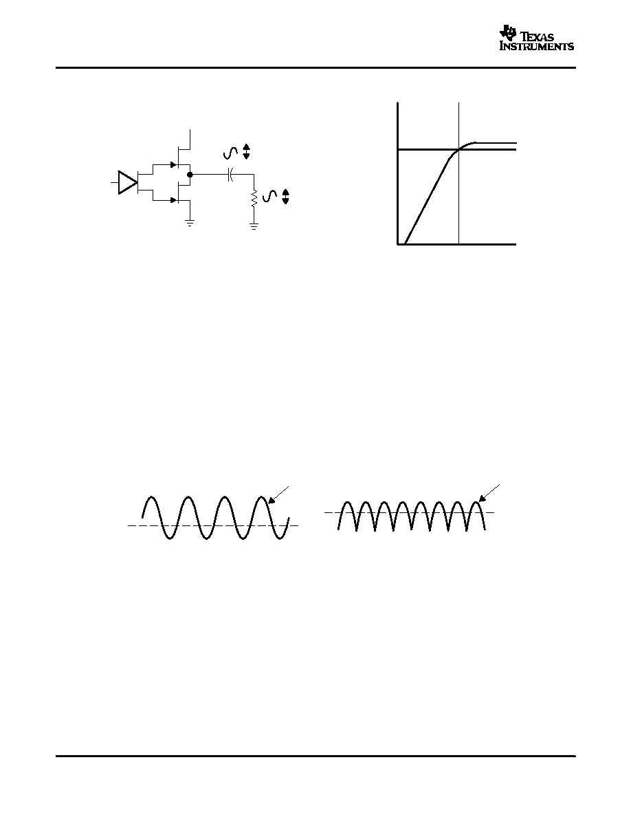
Figure 24. Single-Ended Configuration and Frequency Response
Increasing power to the load does carry a penalty of increased internal power dissipation. The increased
dissipation is understandable considering that the BTL configuration produces 4
× the output power of a SE
configuration. Internal dissipation versus output power is discussed further in the thermal considerations section.
Linear amplifiers are notoriously inefficient. The primary cause of these inefficiencies is voltage drop across the
output stage transistors. There are two components of the internal voltage drop. One is the headroom or dc
voltage drop that varies inversely to output power. The second component is due to the sine-wave nature of the
output. The total voltage drop can be calculated by subtracting the RMS value of the output voltage from VDD.
The internal voltage drop multiplied by the RMS value of the supply current, IDD(RMS), determines the internal
power dissipation of the amplifier.
An easy-to-use equation to calculate efficiency starts out as being equal to the ratio of power from the power
supply to the power delivered to the load. To accurately calculate the RMS values of power in the load and in the
amplifier, the current and voltage waveform shapes must first be understood (see Figure 25).
Figure 25. Voltage and Current Waveforms for BTL Amplifiers
Although the voltages and currents for SE and BTL are sinusoidal in the load, currents from the supply are
different between SE and BTL configurations. In an SE application the current waveform is a half-wave rectified
shape, whereas in BTL it is a full-wave rectified waveform. This means RMS conversion factors are different.
Keep in mind that for most of the waveform both the push and pull transistors are not on at the same time, which
supports the fact that each amplifier in the BTL device only draws current from the supply for half the waveform.
The following equations are the basis for calculating amplifier efficiency.
14
相關PDF資料 |
PDF描述 |
|---|---|
| TPA302DRG4 | 0.3 W, 2 CHANNEL, AUDIO AMPLIFIER, PDSO8 |
| TPA302DG4 | 0.3 W, 2 CHANNEL, AUDIO AMPLIFIER, PDSO8 |
| TPA302D | 0.3 W, 2 CHANNEL, AUDIO AMPLIFIER, PDSO8 |
| TPA302DR | 0.3 W, 2 CHANNEL, AUDIO AMPLIFIER, PDSO8 |
| TPA302Y | 0.3 W, 2 CHANNEL, AUDIO AMPLIFIER, UUC8 |
相關代理商/技術參數 |
參數描述 |
|---|---|
| TPA301EVM | 功能描述:音頻 IC 開發工具 TPA301 Eval Mod RoHS:否 制造商:Texas Instruments 產品:Evaluation Kits 類型:Audio Amplifiers 工具用于評估:TAS5614L 工作電源電壓:12 V to 38 V |
| TPA302 | 制造商:TI 制造商全稱:Texas Instruments 功能描述:300-mW STEREO AUDIO POWER AMPLIFIER |
| TPA302_07 | 制造商:TI 制造商全稱:Texas Instruments 功能描述:300-mW STEREO AUDIO POWER AMPLIFIER |
| TPA3020D2PWPR | 制造商:Texas Instruments 功能描述:LINEAR IC |
| TPA302D | 功能描述:音頻放大器 0.3W Stereo Audio RoHS:否 制造商:STMicroelectronics 產品:General Purpose Audio Amplifiers 輸出類型:Digital 輸出功率: THD + 噪聲: 工作電源電壓:3.3 V 電源電流: 最大功率耗散: 最大工作溫度: 安裝風格:SMD/SMT 封裝 / 箱體:TQFP-64 封裝:Reel |
發布緊急采購,3分鐘左右您將得到回復。