- 您現在的位置:買賣IC網 > PDF目錄98276 > TPA6132A2RTET (TEXAS INSTRUMENTS INC) 0.025 W, 2 CHANNEL, AUDIO AMPLIFIER, PQCC16 PDF資料下載
參數資料
| 型號: | TPA6132A2RTET |
| 廠商: | TEXAS INSTRUMENTS INC |
| 元件分類: | 音頻/視頻放大 |
| 英文描述: | 0.025 W, 2 CHANNEL, AUDIO AMPLIFIER, PQCC16 |
| 封裝: | 3 X 3 MM, GREEN, PLASTIC, QFN-16 |
| 文件頁數: | 4/24頁 |
| 文件大小: | 1166K |
| 代理商: | TPA6132A2RTET |
GAIN CONTROL
HEADPHONE AMPLIFIERS
f
=
c
1
2 R C
p
L
O
(1)
O
C
L
1
C
=
2
R
p
(2)
SLOS597 – DECEMBER 2008 ........................................................................................................................................................................................... www.ti.com
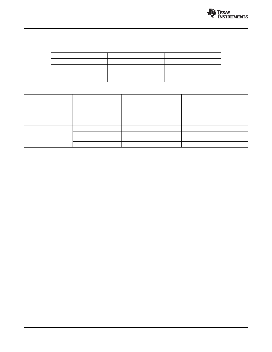
The TPA6132A2 has four gain settings which are controlled with pins G0 and G1. The following table gives an
overview of the gain function.
G0 VOLTAGE
G1 VOLTAGE
AMPLIFIER GAIN
≤ 0.5 V
–6 dB
≥ 1.3 V
≤ 0.5 V
0 dB
≤ 0.5 V
≥ 1.3 V
3 dB
≥ 1.3 V
6 dB
Table 1. Windows Vista Premium Mobile Mode Specifications
Windows Premium Mobile Vista
Device Type
Requirement
TPA6132A2 Typical Performance
Specifications
THD+N
≤ –65 dB FS [20 Hz, 20 kHz]
–75 dB FS[20 Hz, 20 kHz]
Analog Speaker Line Jack
Dynamic Range with Signal
(RL = 10 k, FS = 0.707
≤ –80 dB FS A-Weight
–100 dB FS A-Weight
Present
Vrms)
Line Output Crosstalk
≤ –60 dB [20 Hz, 20 kHz]
–90 dB [20 Hz, 20 kHz]
THD+N
≤ –45 dB FS [20 Hz, 20 kHz]
–65 dB FS [20 Hz, 20 kHz]
Analog Headphone Out Jack
Dynamic Range with Signal
(RL = 32, FS = 0.300
≤ –80 dB FS A-Weight
–94 dB FS A-Weight
Present
Vrms)
Headphone Output Crosstalk
≤ –60 dB [20 Hz, 20 kHz]
–90 dB [20 Hz, 20 kHz]
Single-supply headphone amplifiers typically require dc-blocking capacitors to remove dc bias from their output
voltage. The top drawing in Figure 25 illustrates this connection. If dc bias is not removed, large dc current will
flow through the headphones which wastes power, clip the output signal, and potentially damage the
headphones.
These dc-blocking capacitors are often large in value and size. Headphone speakers have a typical resistance
between 16
and 32 . This combination creates a high-pass filter with a cutoff frequency as shown in
Equation 1, where RL is the load impedance, CO is the dc-block capacitor, and fC is the cutoff frequency.
For a given high-pass cutoff frequency and load impedance, the required dc-blocking capacitor is found as:
Reducing fC improves low frequency fidelity and requires a larger dc-blocking capacitor. To achieve a 20 Hz
cutoff with 16
headphones, CO must be at least 500 F. Large capacitor values require large packages,
consuming PCB area, increasing height, and increasing cost of assembly. During start-up or shutdown the
dc-blocking capacitor has to be charged or discharged. This causes an audible pop on start-up and power-down.
Large dc-blocking capacitors also reduce audio output signal fidelity.
Two different headphone amplifier architectures are available to eliminate the need for dc-blocking capacitors.
The Capless amplifier architecture is similar provides a reference voltage to the headphone connector shield pin
as shown in the middle drawing of Figure 25. The audio output signals are centered around this reference
voltage, which is typically half of the supply voltage to allow symmetrical output voltage swing.
When using a Capless amplifier do not connect the headphone jack shield to any ground reference or large
currents will result. This makes Capless amplifiers ineffective for plugging non-headphone accessories into the
headphone connector. Capless amplifiers are useful only with floating GND headphones.
12
Copyright 2008, Texas Instruments Incorporated
Product Folder Link(s) :TPA6132A2
相關PDF資料 |
PDF描述 |
|---|---|
| TPA6135A2RTER | 0.025 W, 2 CHANNEL, AUDIO AMPLIFIER, PQCC16 |
| TPA6135A2RTET | 0.025 W, 2 CHANNEL, AUDIO AMPLIFIER, PQCC16 |
| TPA6138A2PWR | 0.04 W, 2 CHANNEL, AUDIO AMPLIFIER, PDSO14 |
| TPA6138A2PW | 0.04 W, 2 CHANNEL, AUDIO AMPLIFIER, PDSO14 |
| TPA6139A2PWR | 0.025 W, 2 CHANNEL, AUDIO AMPLIFIER, PDSO14 |
相關代理商/技術參數 |
參數描述 |
|---|---|
| TPA6132A2RTET | 制造商:Texas Instruments 功能描述:Audio Power Amplifier IC 制造商:Texas Instruments 功能描述:IC, AUDIO PWR AMP, CLASS AB, 25mW QFN-16 |
| TPA6133A2 | 制造商:TI 制造商全稱:Texas Instruments 功能描述:138-mW DIRECTPATH STEREO HEADPHONE AMPLIFIER |
| TPA6133A2EVM | 制造商:Texas Instruments 功能描述:TPA6133A2EVM - Boxed Product (Development Kits) 制造商:Texas Instruments 功能描述:EVAL BOARD FOR TPA6133A2 |
| TPA6133A2RTJR | 制造商:Texas Instruments 功能描述:IC AMP AUDIO .138W STER AB 20WQF 制造商:Texas Instruments 功能描述:TPA6133A2RTJR |
| TPA6133A2RTJT | 制造商:TI 制造商全稱:Texas Instruments 功能描述:138-mW DIRECTPATH STEREO HEADPHONE AMPLIFIER |
發布緊急采購,3分鐘左右您將得到回復。