- 您現在的位置:買賣IC網 > PDF目錄69502 > TPS2301IPWR (TEXAS INSTRUMENTS INC) 2-CHANNEL POWER SUPPLY SUPPORT CKT, PDSO20 PDF資料下載
參數資料
| 型號: | TPS2301IPWR |
| 廠商: | TEXAS INSTRUMENTS INC |
| 元件分類: | 電源管理 |
| 英文描述: | 2-CHANNEL POWER SUPPLY SUPPORT CKT, PDSO20 |
| 封裝: | PLASTIC, TSSOP-20 |
| 文件頁數: | 1/24頁 |
| 文件大小: | 644K |
| 代理商: | TPS2301IPWR |
www.ti.com
FEATURES
APPLICATIONS
DESCRIPTION
1
2
3
4
5
6
7
8
9
10
20
19
18
17
16
15
14
13
12
11
GATE1
GATE2
DGND
TIMER
VREG
VSENSE2
VSENSE1
AGND
ISENSE2
ISENSE1
DISCH1
DISCH2
ENABLE
PWRGD1
FAULT
ISET1
ISET2
PWRGD2
IN2
IN1
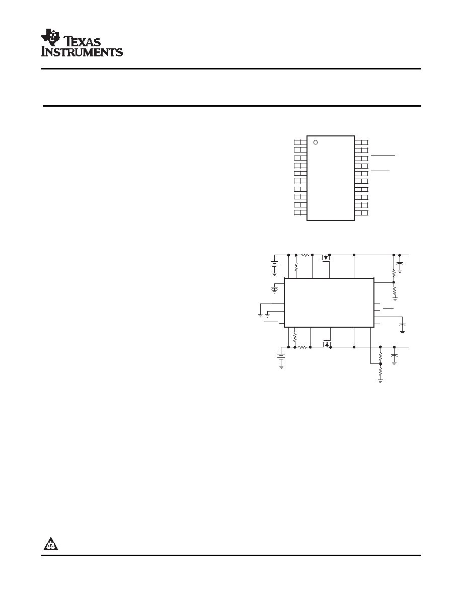
PW PACKAGE
(TOP VIEW)
typical application
NOTE: Terminal 18 is active high on TPS2311.
VREG
IN1
ISET1
ISENSE1 GATE1
DISCH1
VSENSE1
PWRGD1
TIMER
VSENSE2
DISCH2
GATE2
ISENSE2
ISET2
IN2
DGND
AGND
V2
V1
3 V 5.5 V
3 V 13 V
PWRGD2
TPS2310
+
VO1
VO2
ENABLE
FAULT
+
SLVS275G – FEBRUARY 2000 – REVISED NOVEMBER 2006
DUAL HOT-SWAP POWER CONTROLLERS WITH INTERDEPENDENT
CIRCUIT BREAKER AND POWER-GOOD REPORTING
Dual-Channel High-Side MOSFET Drivers
IN1: 3 V to 13 V; IN2: 3 V to 5.5 V
Output dV/dt Control Limits Inrush Current
Circuit-Breaker With Programmable
Overcurrent Threshold and Transient Timer
Power-Good Reporting With Transient Filter
CMOS- and TTL-Compatible Enable Input
Low, 5-A Standby Supply Current .(Max)
Available in 20-Pin TSSOP Package
–40°C to 85°C Ambient Temperature Range
Electrostatic Discharge Protection
Hot-Swap/Plug/Dock Power Management
Hot-Plug PCI, Device Bay
Electronic Circuit Breaker
The
TPS2310
and
TPS2311
are
dual-channel
hot-swap controllers that use external N-channel
MOSFETs
as
high-side
switches
in
power
applications. Features of these devices, such as
overcurrent protection (OCP), inrush current control,
output-power status reporting, and the ability to
discriminate between load transients and faults, are
critical requirements for hot-swap applications.
The TPS2310/11 devices incorporate undervoltage lockout (UVLO) and power-good (PG) reporting to ensure
the device is off at start-up and confirm the status of the output voltage rails during operation. Each internal
charge pump, capable of driving multiple MOSFETs, provides enough gate-drive voltage to fully enhance the
N-channel MOSFETs. The charge pumps control both the rise times and fall times (dv/dt) of the MOSFETs,
reducing power transients during power up/down. The circuit-breaker functionality combines the ability to sense
overcurrent conditions with a timer function; this allows designs such as DSPs, that may have high peak
currents during power-state transitions, to disregard transients for a programmable period.
Please be aware that an important notice concerning availability, standard warranty, and use in critical applications of Texas
Instruments semiconductor products and disclaimers thereto appears at the end of this data sheet.
PRODUCTION DATA information is current as of publication date.
Copyright 2000–2006, Texas Instruments Incorporated
Products conform to specifications per the terms of the Texas
Instruments standard warranty. Production processing does not
necessarily include testing of all parameters.
相關PDF資料 |
PDF描述 |
|---|---|
| TPS2311IPW | 2-CHANNEL POWER SUPPLY SUPPORT CKT, PDSO20 |
| TPS2321IDR | 2-CHANNEL POWER SUPPLY SUPPORT CKT, PDSO16 |
| TPS2321IPWG4 | 2-CHANNEL POWER SUPPLY SUPPORT CKT, PDSO16 |
| TPS2320IPWR | 2-CHANNEL POWER SUPPLY SUPPORT CKT, PDSO16 |
| TPS2321IPWRG4 | 2-CHANNEL POWER SUPPLY SUPPORT CKT, PDSO16 |
相關代理商/技術參數 |
參數描述 |
|---|---|
| TPS2301IPWRG4 | 功能描述:熱插拔功率分布 3-13V Dual w/Ind Chl Circuit Breaking RoHS:否 制造商:Texas Instruments 產品:Controllers & Switches 電流限制: 電源電壓-最大:7 V 電源電壓-最小:- 0.3 V 工作溫度范圍: 功率耗散: 安裝風格:SMD/SMT 封裝 / 箱體:MSOP-8 封裝:Tube |
| TPS2306DW | 功能描述:DUAL SEQ HOT SWAP PWR M 16-SOIC RoHS:是 類別:集成電路 (IC) >> PMIC - 熱交換 系列:- 產品培訓模塊:Obsolescence Mitigation Program 標準包裝:100 系列:- 類型:熱插拔開關 應用:通用 內部開關:是 電流限制:可調 電源電壓:9 V ~ 13.2 V 工作溫度:-40°C ~ 150°C 安裝類型:表面貼裝 封裝/外殼:10-WFDFN 裸露焊盤 供應商設備封裝:10-TDFN-EP(3x3) 包裝:管件 |
| TPS2306DWG4 | 制造商:Texas Instruments 功能描述: |
| TPS2306EVM-001 | 功能描述:EVALUATION MODULE FOR TPS2306 RoHS:是 類別:編程器,開發系統 >> 評估演示板和套件 系列:- 產品培訓模塊:Obsolescence Mitigation Program 標準包裝:1 系列:- 主要目的:電源管理,電池充電器 嵌入式:否 已用 IC / 零件:MAX8903A 主要屬性:1 芯鋰離子電池 次要屬性:狀態 LED 已供物品:板 |
| TPS230QP | 制造商:Texas Instruments 功能描述: |
發布緊急采購,3分鐘左右您將得到回復。