- 您現(xiàn)在的位置:買賣IC網(wǎng) > PDF目錄98283 > TPS54372PWP (TEXAS INSTRUMENTS INC) 3 A SWITCHING REGULATOR, 762 kHz SWITCHING FREQ-MAX, PDSO20 PDF資料下載
參數(shù)資料
| 型號: | TPS54372PWP |
| 廠商: | TEXAS INSTRUMENTS INC |
| 元件分類: | 穩(wěn)壓器 |
| 英文描述: | 3 A SWITCHING REGULATOR, 762 kHz SWITCHING FREQ-MAX, PDSO20 |
| 封裝: | GREEN, PLASTIC, HTSSOP-20 |
| 文件頁數(shù): | 4/18頁 |
| 文件大小: | 525K |
| 代理商: | TPS54372PWP |
www.ti.com
DETAILED DESCRIPTION
UNDERVOLTAGE LOCKOUT (UVLO)
VOLTAGE REFERENCE
OSCILLATOR AND PWM RAMP
ENABLE (ENA)
Switching Frequency +
100 kW
R
500 [kHz]
SLOW-START
ERROR AMPLIFIER
PWM CONTROL
VBIAS REGULATOR (VBIAS)
TPS54372
SLVS430D – JUNE 2002 – REVISED FEBRUARY 2005
The TPS54372 incorporates an undervoltage lockout
The REFIN pin provides an input for a user supplied
circuit to keep the device disabled when the input
tracking voltage. Typically this input is one half of
voltage (VIN) is insufficient. During power up, internal
VDDQ. The input range for this external reference is
circuits are held inactive until VIN exceeds the
0.2 V to 1.75 V. Above this level, the internal
nominal UVLO threshold voltage of 2.95 V. Once the
bandgap reference overrides the externally supplied
UVLO start threshold is reached, device start-up
reference voltage.
begins. The device operates until VIN falls below the
nominal UVLO comparator. Hysteresis in the UVLO
comparator, and a 2.5-s rising and falling edge
The oscillator frequency can be set to an internally
deglitch circuit reduce the likelihood of shutting the
fixed value of 350 kHz by leaving the RT pin
device down due to noise on VIN.
unconnected (floating). If a different frequency of
operation is required for the application, the oscillator
frequency can be externally adjusted from 280 to 700
The enable pin, ENA, provides a digital control to
kHz by connecting a resistor to the RT pin to ground.
enable or disable (shutdown) the TPS54372. An input
The switching frequency is approximated by the
voltage of 1.4 V or greater ensures the TPS54372 is
following equation, where R is the resistance from RT
enabled. An input of 0.82 V or less ensures the
to AGND:
device operation is disabled. These are not standard
logic thresholds, even though they are compatible
with TTL outputs.
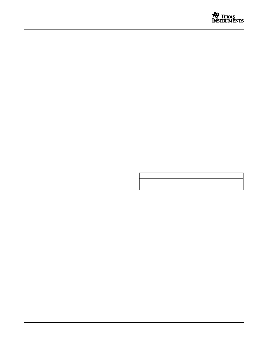
The following table summarizes the frequency selec-
When ENA is low, the oscillator, slow-start, PWM
tion configurations:
control and MOSFET drivers are disabled and held in
an initial state ready for device start-up. On an ENA
Frequency Selection
transition from low to high, device start-up begins with
SWITCHING FREQUENCY
RT PIN
the output starting from 0 V.
350 kHz, internally set
Float
Externally set 280 kHz to 700 kHz
R = 180 k
to 68 k
The slow-start circuit provides start-up slope control
of the output voltage to limit in-rush currents. The
nominal internal slow-start rate is 0.25 V/ms with the
The high-performance, wide bandwidth, voltage error
minimum rate being 0.35 V/ms. When the voltage on
amplifier sets the TPS54372 apart from most dc/dc
REFIN rises faster than the internal slope or is
converters. The user has a wide range of output L
present when device operation is enabled, the output
and C filter components to suit the particular appli-
rises at the internal rate. If the reference voltage on
cation needs. Type-2 or type-3 compensation can be
REFIN rises more slowly, then the output rises at
employed using external compensation components.
approximately the same rate as REFIN.
Signals from the error amplifier output, oscillator, and
The VBIAS regulator provides internal analog and
current limit circuit are processed by the PWM control
digital blocks with a stable supply voltage over
logic. Referring to the internal block diagram, the
variations in junction temperature and input voltage. A
control logic includes the PWM comparator, OR gate,
high quality, low-ESR, ceramic bypass capacitor is
PWM latch, and portions of the adaptive dead-time
required on the VBIAS pin. X7R- or X5R-grade
and control logic block. During steady-state operation
dielectrics are recommended because their values
below
the
current
limit
threshold,
the
PWM
are more stable over temperature. The bypass ca-
comparator output and oscillator pulse train alter-
pacitor should be placed close to the VBIAS pin and
nately reset and set the PWM latch. Once the PWM
returned to AGND. External loading on VBIAS is
latch is set, the low-side FET remains on for a
allowed, with the caution that internal circuits require
minimum duration set by the oscillator pulse width.
a minimum VBIAS of 2.7 V, and external loads on
During this period, the PWM ramp discharges rapidly
VBIAS with ac or digital switching noise may degrade
to its valley voltage. When the ramp begins to charge
performance. The VBIAS pin may be useful as a
back up, the low-side FET turns off and high-side
reference voltage for external circuits.
FET turns on. As the PWM ramp voltage exceeds the
12
相關(guān)PDF資料 |
PDF描述 |
|---|---|
| TPS54418RTER | 6.4 A SWITCHING REGULATOR, 2000 kHz SWITCHING FREQ-MAX, PQCC16 |
| TPS54426PWP | 7.5 A SWITCHING REGULATOR, 700 kHz SWITCHING FREQ-MAX, PDSO14 |
| TPS54429PWP | 0.01 A SWITCHING REGULATOR, 700 kHz SWITCHING FREQ-MAX, PDSO14 |
| TPS5450MDDAREP | 11.7 A SWITCHING REGULATOR, 600 kHz SWITCHING FREQ-MAX, PDSO8 |
| TPS54519RTER | 8 A SWITCHING REGULATOR, 2000 kHz SWITCHING FREQ-MAX, PQCC16 |
相關(guān)代理商/技術(shù)參數(shù) |
參數(shù)描述 |
|---|---|
| TPS54372PWP | 制造商:Texas Instruments 功能描述:; Voltage Regulator Type:Synchronous Buc |
| TPS54372PWPG4 | 功能描述:直流/直流開關(guān)調(diào)節(jié)器 3-A Act Bus Term/DDR DC/DC Converter RoHS:否 制造商:International Rectifier 最大輸入電壓:21 V 開關(guān)頻率:1.5 MHz 輸出電壓:0.5 V to 0.86 V 輸出電流:4 A 輸出端數(shù)量: 最大工作溫度: 安裝風(fēng)格:SMD/SMT 封裝 / 箱體:PQFN 4 x 5 |
| TPS54372PWPR | 功能描述:直流/直流開關(guān)調(diào)節(jié)器 3-A Act Bus Term/DDR DC/DC Converter RoHS:否 制造商:International Rectifier 最大輸入電壓:21 V 開關(guān)頻率:1.5 MHz 輸出電壓:0.5 V to 0.86 V 輸出電流:4 A 輸出端數(shù)量: 最大工作溫度: 安裝風(fēng)格:SMD/SMT 封裝 / 箱體:PQFN 4 x 5 |
| TPS54372PWPRG4 | 功能描述:直流/直流開關(guān)調(diào)節(jié)器 3-A Act Bus Term/DDR DC/DC Converter RoHS:否 制造商:International Rectifier 最大輸入電壓:21 V 開關(guān)頻率:1.5 MHz 輸出電壓:0.5 V to 0.86 V 輸出電流:4 A 輸出端數(shù)量: 最大工作溫度: 安裝風(fēng)格:SMD/SMT 封裝 / 箱體:PQFN 4 x 5 |
| TPS54372QPWPRQ1 | 功能描述:直流/直流開關(guān)調(diào)節(jié)器 3A Output Tracking/ Term Sync PWM Sw RoHS:否 制造商:International Rectifier 最大輸入電壓:21 V 開關(guān)頻率:1.5 MHz 輸出電壓:0.5 V to 0.86 V 輸出電流:4 A 輸出端數(shù)量: 最大工作溫度: 安裝風(fēng)格:SMD/SMT 封裝 / 箱體:PQFN 4 x 5 |
發(fā)布緊急采購,3分鐘左右您將得到回復(fù)。