- 您現在的位置:買賣IC網 > PDF目錄98283 > TPS5602IDBTR (TEXAS INSTRUMENTS INC) 3 A DUAL SWITCHING CONTROLLER, 202.4 kHz SWITCHING FREQ-MAX, PDSO30 PDF資料下載
參數資料
| 型號: | TPS5602IDBTR |
| 廠商: | TEXAS INSTRUMENTS INC |
| 元件分類: | 穩壓器 |
| 英文描述: | 3 A DUAL SWITCHING CONTROLLER, 202.4 kHz SWITCHING FREQ-MAX, PDSO30 |
| 封裝: | GREEN, PLASTIC, TSSOP-30 |
| 文件頁數: | 23/27頁 |
| 文件大小: | 949K |
| 代理商: | TPS5602IDBTR |
第1頁第2頁第3頁第4頁第5頁第6頁第7頁第8頁第9頁第10頁第11頁第12頁第13頁第14頁第15頁第16頁第17頁第18頁第19頁第20頁第21頁第22頁當前第23頁第24頁第25頁第26頁第27頁
TPS5602
DUAL, FAST, HIGH EFFICIENCY CONTROLLER FOR DSP POWER
SLVS217 – JUNE 1999
5
POST OFFICE BOX 655303
DALLAS, TEXAS 75265
absolute maximum ratings over operating free-air temperature (see Note 1) (unless otherwise
noted)
Supply voltage, VCC
–0.3 V to 27 V
. . . . . . . . . . . . . . . . . . . . . . . . . . . . . . . . . . . . . . . . . . . . . . . . . . . . . . . . . . . . . .
Input voltage, VI, INV
–0.3 V to 7 V
. . . . . . . . . . . . . . . . . . . . . . . . . . . . . . . . . . . . . . . . . . . . . . . . . . . . . . . . . . . . . . .
Softstart
–0.3 V to 7 V
. . . . . . . . . . . . . . . . . . . . . . . . . . . . . . . . . . . . . . . . . . . . . . . . . . . . . . . . . . .
COMP
–0.3 V to 6 V
. . . . . . . . . . . . . . . . . . . . . . . . . . . . . . . . . . . . . . . . . . . . . . . . . . . . . . . . . . . .
REG5V_IN
–0.3 V to 6 V
. . . . . . . . . . . . . . . . . . . . . . . . . . . . . . . . . . . . . . . . . . . . . . . . . . . . . . . .
STBY
–0.3 V to 15 V
. . . . . . . . . . . . . . . . . . . . . . . . . . . . . . . . . . . . . . . . . . . . . . . . . . . . . . . . . . . .
TRIP
–0.3 V to 15 V
. . . . . . . . . . . . . . . . . . . . . . . . . . . . . . . . . . . . . . . . . . . . . . . . . . . . . . . . . . . . .
Maximum Driver current
3 A
. . . . . . . . . . . . . . . . . . . . . . . . . . . . . . . . . . . . . . . . . . . . . . . . . . . . . . . . . . . . . . . . . . . . .
Output voltage, LLx
–0.3 V to 27 V
. . . . . . . . . . . . . . . . . . . . . . . . . . . . . . . . . . . . . . . . . . . . . . . . . . . . . . . . . . . . . . .
Output voltage, OUTx_u
–0.3 V to 32 V
. . . . . . . . . . . . . . . . . . . . . . . . . . . . . . . . . . . . . . . . . . . . . . . . . . . . . . . . . . .
Output voltage, OUTx_d
–0.3 V to 7 V
. . . . . . . . . . . . . . . . . . . . . . . . . . . . . . . . . . . . . . . . . . . . . . . . . . . . . . . . . . . .
Power dissipation (TA = 25°C)
See Dissipation Table
. . . . . . . . . . . . . . . . . . . . . . . . . . . . . . . . . . . . . . . . . . . . . . . .
Operating free-air temperature range, TA
– 40
°C to 85°C
. . . . . . . . . . . . . . . . . . . . . . . . . . . . . . . . . . . . . . . . . . . .
Operating virtual junction temperature range, TJ
125
°C
. . . . . . . . . . . . . . . . . . . . . . . . . . . . . . . . . . . . . . . . . . . . .
Storage temperature range, Tstg
– 55
°C to 150°C
. . . . . . . . . . . . . . . . . . . . . . . . . . . . . . . . . . . . . . . . . . . . . . . . . . .
Stresses beyond those listed under “absolute maximum ratings” may cause permanent damage to the device. These are stress ratings only, and
functional operation of the device at these or any other conditions beyond those indicated under “recommended operating conditions” is not
implied. Exposure to absolute-maximum-rated conditions for extended periods may affect device reliability.
NOTE 1: All voltages are with respect to GND terminal.
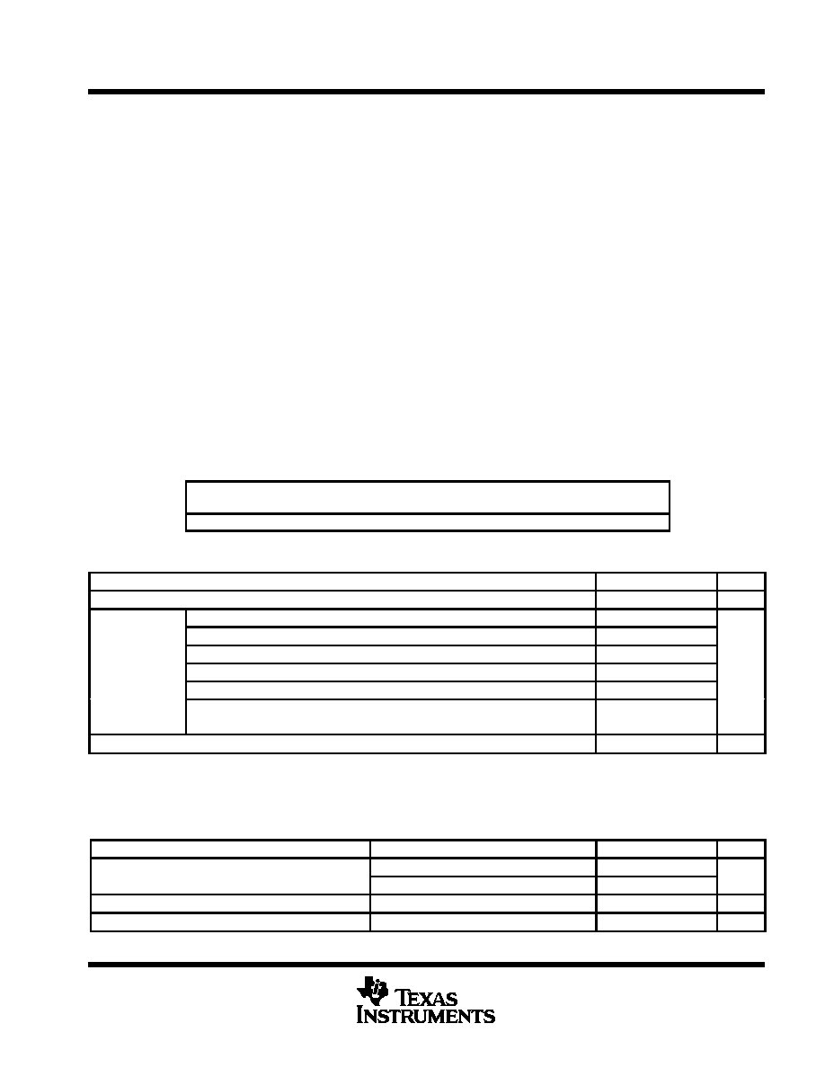
DISSIPATION RATING TABLE
PACKAGE
TA = 25°C
POWER DISSIPATION
TA ≥ 25°C
DERATING FACTOR
TA = 85°C
POWER DISSIPATION
DBT
874 mW
6.993 mW/
°C
454 mW
recommended operating conditions
MIN
NOM
MAX
UNIT
Supply voltage, VCC
4.5
25
V
INV1/2
6
COMP
6
SOFTSTART1/2
6
Input voltage, VI
REG5V_IN
5.5
V
STBY1/STBY2
12
TRIP1/2
25
VCC_SENCE
25
Operation junction temperature range, TA
–40
85
°C
electrical characteristics over recommended TA = –40°C to 85°C temperature range, VCC = 7 V
(unless otherwise noted)
reference voltage
PARAMETER
TEST CONDITIONS
MIN
TYP
MAX
UNIT
V f
Reference voltage
TA = 25°C,
Ivref = 50 A
1.167
1.185
1.203
V
Vref
Reference voltage
VI = 4.5 V to 25 V,
I = 1
A to 1 mA
1.155
1.215
V
VI(Regin)
Line regulation
VCC = 5.5 V to 25 V,
I = 50
A
0.2
12
mV
VI(Regl)
Load regulation
I = 1
A to 1 mA,
0.5
10
mV
相關PDF資料 |
PDF描述 |
|---|---|
| TPS561000PWP | 1.4 A SWITCHING CONTROLLER, PDSO28 |
| TPS56100PWPR | 1.4 A SWITCHING CONTROLLER, 500 kHz SWITCHING FREQ-MAX, PDSO28 |
| TPS56100PWPRG4 | 1.4 A SWITCHING CONTROLLER, 500 kHz SWITCHING FREQ-MAX, PDSO28 |
| TPS56121DQPT | SWITCHING CONTROLLER, 1100 kHz SWITCHING FREQ-MAX, PDSO22 |
| TPS5615CPWP | SWITCHING CONTROLLER, PDSO28 |
相關代理商/技術參數 |
參數描述 |
|---|---|
| TPS5602IDBTRG4 | 功能描述:DC/DC 開關控制器 Dual Output Synch Buck Cntrlr RoHS:否 制造商:Texas Instruments 輸入電壓:6 V to 100 V 開關頻率: 輸出電壓:1.215 V to 80 V 輸出電流:3.5 A 輸出端數量:1 最大工作溫度:+ 125 C 安裝風格: 封裝 / 箱體:CPAK |
| TPS56100EVM-128 | 功能描述:HIGH-PERFORMANCE SYNCHRONOUS BUC RoHS:是 類別:編程器,開發系統 >> 評估板 - DC/DC 與 AC/DC(離線)SMPS 系列:- 產品培訓模塊:Obsolescence Mitigation Program 標準包裝:1 系列:True Shutdown™ 主要目的:DC/DC,步升 輸出及類型:1,非隔離 功率 - 輸出:- 輸出電壓:- 電流 - 輸出:1A 輸入電壓:2.5 V ~ 5.5 V 穩壓器拓撲結構:升壓 頻率 - 開關:3MHz 板類型:完全填充 已供物品:板 已用 IC / 零件:MAX8969 |
| TPS56100EVM-133 | 功能描述:HIGH-PERFORMANCE SYNCHRONOUS BUC RoHS:是 類別:編程器,開發系統 >> 評估板 - DC/DC 與 AC/DC(離線)SMPS 系列:- 產品培訓模塊:Obsolescence Mitigation Program 標準包裝:1 系列:True Shutdown™ 主要目的:DC/DC,步升 輸出及類型:1,非隔離 功率 - 輸出:- 輸出電壓:- 電流 - 輸出:1A 輸入電壓:2.5 V ~ 5.5 V 穩壓器拓撲結構:升壓 頻率 - 開關:3MHz 板類型:完全填充 已供物品:板 已用 IC / 零件:MAX8969 |
| TPS56100PWP | 功能描述:DC/DC 開關控制器 5 Bit Programmable Sync Buck Cont RoHS:否 制造商:Texas Instruments 輸入電壓:6 V to 100 V 開關頻率: 輸出電壓:1.215 V to 80 V 輸出電流:3.5 A 輸出端數量:1 最大工作溫度:+ 125 C 安裝風格: 封裝 / 箱體:CPAK |
| TPS56100PWPG4 | 功能描述:DC/DC 開關控制器 5 Bit Programmable Sync Buck Cont RoHS:否 制造商:Texas Instruments 輸入電壓:6 V to 100 V 開關頻率: 輸出電壓:1.215 V to 80 V 輸出電流:3.5 A 輸出端數量:1 最大工作溫度:+ 125 C 安裝風格: 封裝 / 箱體:CPAK |
發布緊急采購,3分鐘左右您將得到回復。