- 您現在的位置:買賣IC網 > PDF目錄382680 > TPS62229DDC (Texas Instruments, Inc.) 400-mA, 1.25-MHz, HIGH-EFFICIENCY, STEP-DOWN CONVERTER IN THIN-SOT23 PDF資料下載
參數資料
| 型號: | TPS62229DDC |
| 廠商: | Texas Instruments, Inc. |
| 英文描述: | 400-mA, 1.25-MHz, HIGH-EFFICIENCY, STEP-DOWN CONVERTER IN THIN-SOT23 |
| 中文描述: | 400毫安,1.25 MHz的,高效率,降壓型轉換器薄,SOT23封裝 |
| 文件頁數: | 14/20頁 |
| 文件大小: | 464K |
| 代理商: | TPS62229DDC |
www.ti.com
C2
1
2
P
R2
1
2
8 kHz
R2
V
I
GND
EN
SW
FB
C3
4.7
μ
F
L1
4.7
μ
H
C4
10
μ
F
TPS62220
V
I
2.5 V 6 V
V
O
1.8 V / 400 mA
R1
470k
R2
180k
C1
15 pF
C2
100 pF
INDUCTOR SELECTION
For high efficiencies, the inductor should have a low dc resistance to minimize conduction losses. Especially at
high switching frequencies the core material has a higher impact on efficiency. When using small chip inductors,
the efficiency is reduced mainly due to higher inductor core losses. This needs to be considered when selecting
the appropriate inductor. The inductor value determines the inductor ripple current. The larger the inductor value,
the smaller the inductor ripple current and the lower the conduction losses of the converter. Conversely, larger
inductor values cause a slower load transient response. To avoid saturation of the inductor, the inductor should
be rated at least for the maximum output current of the converter plus the inductor ripple current that is
calculated as
IL
Vout
1–Vout
Vin
L
f
I
Lmax
I
outmax
IL
2
f = switching frequency (1.25 MHz typical, 800 kHz minimal)
L = inductor value
I
L
= peak-to-peak inductor ripple current
I
Lmax
= maximum inductor current
TPS62220, TPS62221, TPS62222
TPS62223, TPS62224
TPS62228, TPS62229
SLVS491C–SEPTEMBER 2003–REVISED SEPTEMBER 2004
The pole is calculated as:
with R2 = lower resistor of voltage divider and C2 = lower capacitor of voltage divider.
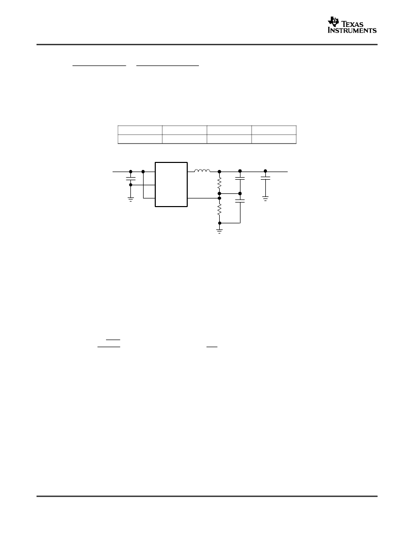
For an output filter combination of L = 4.7 μH and C
O
= 10 μF; C1 and C2 need to be selected to place a zero at
22 kHz and a pole at 8 kHz. Choose components close to the calculated values.
Table 2. Compensation Selection
L
C
O
f
Z
f
P
4.7 μH
10 μF, 22 μF
22 kHz
8 kHz
Figure 15. Typical Application Circuit for the TPS62220 With Adjustable Output Voltage
The highest inductor current occurs at maximum Vin. A more conservative approach is to select the inductor
current rating just for the maximum switch current of 880 mA. SeeTable 3 for inductor selection.
14
相關PDF資料 |
PDF描述 |
|---|---|
| TPS62223DDC | 400-mA, 1.25-MHz, HIGH-EFFICIENCY, STEP-DOWN CONVERTER IN THIN-SOT23 |
| TPS6222 | 400-mA, 1.25-MHz, HIGH-EFFICIENCY, STEP-DOWN CONVERTER IN THIN-SOT23 |
| TPS62228DDC | 400-mA, 1.25-MHz, HIGH-EFFICIENCY, STEP-DOWN CONVERTER IN THIN-SOT23 |
| TPS62304DRC | 500-mA, 3-MHz SYNCHRONOUS STEP-DOWN CONVERTER IN CHIP SCALE PACKAGING |
| TPS62304YZD | 500-mA, 3-MHz SYNCHRONOUS STEP-DOWN CONVERTER IN CHIP SCALE PACKAGING |
相關代理商/技術參數 |
參數描述 |
|---|---|
| TPS62229DDCR | 功能描述:開關變換器、穩壓器與控制器 1.7V Out 400mA Step-Down Converter RoHS:否 制造商:Texas Instruments 輸出電壓:1.2 V to 10 V 輸出電流:300 mA 輸出功率: 輸入電壓:3 V to 17 V 開關頻率:1 MHz 工作溫度范圍: 安裝風格:SMD/SMT 封裝 / 箱體:WSON-8 封裝:Reel |
| TPS62229DDCRG4 | 功能描述:開關變換器、穩壓器與控制器 1.7V Out 400mA Step-Down Converter RoHS:否 制造商:Texas Instruments 輸出電壓:1.2 V to 10 V 輸出電流:300 mA 輸出功率: 輸入電壓:3 V to 17 V 開關頻率:1 MHz 工作溫度范圍: 安裝風格:SMD/SMT 封裝 / 箱體:WSON-8 封裝:Reel |
| TPS62229DDCT | 功能描述:直流/直流開關調節器 1.7V Out 400mA Step-Down Converter RoHS:否 制造商:International Rectifier 最大輸入電壓:21 V 開關頻率:1.5 MHz 輸出電壓:0.5 V to 0.86 V 輸出電流:4 A 輸出端數量: 最大工作溫度: 安裝風格:SMD/SMT 封裝 / 箱體:PQFN 4 x 5 |
| TPS62229DDCTG4 | 功能描述:直流/直流開關調節器 1.7V Out 400mA 95% Eff Step-Down Cnvrtr RoHS:否 制造商:International Rectifier 最大輸入電壓:21 V 開關頻率:1.5 MHz 輸出電壓:0.5 V to 0.86 V 輸出電流:4 A 輸出端數量: 最大工作溫度: 安裝風格:SMD/SMT 封裝 / 箱體:PQFN 4 x 5 |
| TPS62230DRYR | 功能描述:直流/直流開關調節器 3 MHz Ultra Small Step Down Converter RoHS:否 制造商:International Rectifier 最大輸入電壓:21 V 開關頻率:1.5 MHz 輸出電壓:0.5 V to 0.86 V 輸出電流:4 A 輸出端數量: 最大工作溫度: 安裝風格:SMD/SMT 封裝 / 箱體:PQFN 4 x 5 |
發布緊急采購,3分鐘左右您將得到回復。