- 您現在的位置:買賣IC網 > PDF目錄98286 > TPS65920BZCH (TEXAS INSTRUMENTS INC) SPECIALTY CONSUMER CIRCUIT, PBGA139 PDF資料下載
參數資料
| 型號: | TPS65920BZCH |
| 廠商: | TEXAS INSTRUMENTS INC |
| 元件分類: | 消費家電 |
| 英文描述: | SPECIALTY CONSUMER CIRCUIT, PBGA139 |
| 封裝: | 10 X 10 MM, 0.65 MM PITCH, GREEN, PLASTIC, NFBGA-139 |
| 文件頁數: | 38/115頁 |
| 文件大小: | 1232K |
| 代理商: | TPS65920BZCH |
第1頁第2頁第3頁第4頁第5頁第6頁第7頁第8頁第9頁第10頁第11頁第12頁第13頁第14頁第15頁第16頁第17頁第18頁第19頁第20頁第21頁第22頁第23頁第24頁第25頁第26頁第27頁第28頁第29頁第30頁第31頁第32頁第33頁第34頁第35頁第36頁第37頁當前第38頁第39頁第40頁第41頁第42頁第43頁第44頁第45頁第46頁第47頁第48頁第49頁第50頁第51頁第52頁第53頁第54頁第55頁第56頁第57頁第58頁第59頁第60頁第61頁第62頁第63頁第64頁第65頁第66頁第67頁第68頁第69頁第70頁第71頁第72頁第73頁第74頁第75頁第76頁第77頁第78頁第79頁第80頁第81頁第82頁第83頁第84頁第85頁第86頁第87頁第88頁第89頁第90頁第91頁第92頁第93頁第94頁第95頁第96頁第97頁第98頁第99頁第100頁第101頁第102頁第103頁第104頁第105頁第106頁第107頁第108頁第109頁第110頁第111頁第112頁第113頁第114頁第115頁
SWCS037G
– MAY 2008 – REVISED APRIL 2011
4.1.1
VDD1 dc-dc Regulator
4.1.1.1
VDD1 dc-dc Regulator Characteristics
The VDD1 dc-dc regulator is a stepdown dc-dc converter with a configurable output voltage. The
programming
of
the
output
voltage
and
the
characteristics
of
the
dc-dc
converter
are
SmartReflex-compatible. The regulator can be put in sleep mode to reduce its leakage (PFM) or in
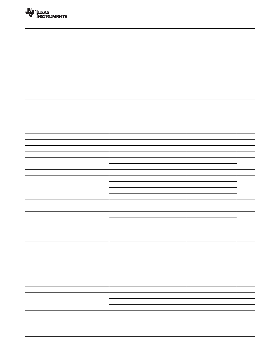
power-down mode when it is not in use. Table 4-3 describes the regulator characteristics.
Table 4-2. Part Names With Corresponding VDD1 Current Support
Device Name
VDD1 Current Support
TPS65920A2ZCH (some bug fixes, see errata)
1.2 A
TPS65920A2ZCHR (some bug fixes, see errata)
1.2 A
TPS65930A2ZCH (some bug fixes, see errata)
1.2 A
TPS65930A2ZCHR (some bug fixes, see errata)
1.2 A
Table 4-3. VDD1 dc-dc Regulator Characteristics
Parameter
Comments
Min
Typ
Max
Unit
Input voltage range
2.7
3.6
4.5
V
Output voltage
0.6
1.45
V
Output voltage step
Covering the 0.6-V to 1.45-V range
12.5
mV
Output accuracy(1)
0.6 V to
< 0.8 V
–6%
6%
0.8 V to 1.45 V
–4%
4%
Switching frequency
3.2
MHz
IO = 10 mA, sleep
82%
100 mA
< IO < 400 mA
85%
mode
400 mA
< IO < 600 mA
80%
600 mA
< IO < 800 mA
75%
Active mode
1.2
A
Output current
Sleep mode
10
mA
Ground current (IQ)
Off at 30
°C
3
μA
Sleep, unloaded
30
50
Active, unloaded, not switching
300
Short-circuit current
VIN = VMax
2.2
A
Load regulation
0
< IO < IMax
20
mV
IO = 10 mA to (IMax/2) + 10 mA,
Transient load regulation(3)
–65
50
mV
Maximum slew rate is IMax/2/100 ns
Line regulation
10
mV
Transient line regulation
300 mVPP ac input, 10-μs rise and fall time
10
mV
Start-up time
0.25
1
ms
Recovery time
From sleep mode to on mode with constant
<10
100
μs
load
Slew rate (rising or falling)(4)
4
8
16
mV/
μs
Output shunt resistor (pulldown)
500
700
Value
0.7
1
1.3
μH
External coil
Data capture record (DCR)
0.1
Saturation current
1.8
A
(1)
Accuracy includes all variations (line and load regulations, line and load transients, temperature, and process)
(2)
VBAT = 3.8 V, VDD1 = 1.3 V, Fs = 3.2 MHz, L = 1
μH, LDCR = 100 m, C = 10 μF, ESR = 10 m
(3)
Output voltage must discharge the load current completely and settle to its final value within 100
μs.
(4)
Load current varies proportionally with the output voltage. The slew rate is for increasing and decreasing voltages, and the maximum
load current is 1.1 A.
Copyright
2008–2011, Texas Instruments Incorporated
Power Module
29
focus.ti.com: TPS65930/TPS65920
相關PDF資料 |
PDF描述 |
|---|---|
| TPS65930A2ZCHR | SPECIALTY CONSUMER CIRCUIT, PBGA139 |
| TPS65930A2ZCH | SPECIALTY CONSUMER CIRCUIT, PBGA139 |
| TPS65930BZCHR | SPECIALTY CONSUMER CIRCUIT, PBGA139 |
| TPS65930BZCH | SPECIALTY CONSUMER CIRCUIT, PBGA139 |
| TPS65950ZXNR | SPECIALTY CONSUMER CIRCUIT, PBGA209 |
相關代理商/技術參數 |
參數描述 |
|---|---|
| TPS65920BZCH | 制造商:Texas Instruments 功能描述:Power Supply IC |
| TPS65920BZCHR | 功能描述:開關變換器、穩壓器與控制器 Int Pwr Mgmt IC RoHS:否 制造商:Texas Instruments 輸出電壓:1.2 V to 10 V 輸出電流:300 mA 輸出功率: 輸入電壓:3 V to 17 V 開關頻率:1 MHz 工作溫度范圍: 安裝風格:SMD/SMT 封裝 / 箱體:WSON-8 封裝:Reel |
| TPS65921B1ZQZ | 功能描述:PMIC 解決方案 Integrated Power Mgmt IC RoHS:否 制造商:Texas Instruments 安裝風格:SMD/SMT 封裝 / 箱體:QFN-24 封裝:Reel |
| TPS65921B1ZQZR | 功能描述:PMIC 解決方案 Integrated Power Mgmt IC RoHS:否 制造商:Texas Instruments 安裝風格:SMD/SMT 封裝 / 箱體:QFN-24 封裝:Reel |
| TPS65921BZQZ | 功能描述:PMIC 解決方案 Int Power Mgmt IC RoHS:否 制造商:Texas Instruments 安裝風格:SMD/SMT 封裝 / 箱體:QFN-24 封裝:Reel |
發布緊急采購,3分鐘左右您將得到回復。