- 您現在的位置:買賣IC網 > PDF目錄98286 > TPS65920BZCHR (TEXAS INSTRUMENTS INC) SPECIALTY CONSUMER CIRCUIT, PBGA139 PDF資料下載
參數資料
| 型號: | TPS65920BZCHR |
| 廠商: | TEXAS INSTRUMENTS INC |
| 元件分類: | 消費家電 |
| 英文描述: | SPECIALTY CONSUMER CIRCUIT, PBGA139 |
| 封裝: | 10 X 10 MM, 0.65 MM PITCH, GREEN, PLASTIC, NFBGA-139 |
| 文件頁數: | 4/115頁 |
| 文件大小: | 1232K |
| 代理商: | TPS65920BZCHR |
第1頁第2頁第3頁當前第4頁第5頁第6頁第7頁第8頁第9頁第10頁第11頁第12頁第13頁第14頁第15頁第16頁第17頁第18頁第19頁第20頁第21頁第22頁第23頁第24頁第25頁第26頁第27頁第28頁第29頁第30頁第31頁第32頁第33頁第34頁第35頁第36頁第37頁第38頁第39頁第40頁第41頁第42頁第43頁第44頁第45頁第46頁第47頁第48頁第49頁第50頁第51頁第52頁第53頁第54頁第55頁第56頁第57頁第58頁第59頁第60頁第61頁第62頁第63頁第64頁第65頁第66頁第67頁第68頁第69頁第70頁第71頁第72頁第73頁第74頁第75頁第76頁第77頁第78頁第79頁第80頁第81頁第82頁第83頁第84頁第85頁第86頁第87頁第88頁第89頁第90頁第91頁第92頁第93頁第94頁第95頁第96頁第97頁第98頁第99頁第100頁第101頁第102頁第103頁第104頁第105頁第106頁第107頁第108頁第109頁第110頁第111頁第112頁第113頁第114頁第115頁
SWCS037G
– MAY 2008 – REVISED APRIL 2011
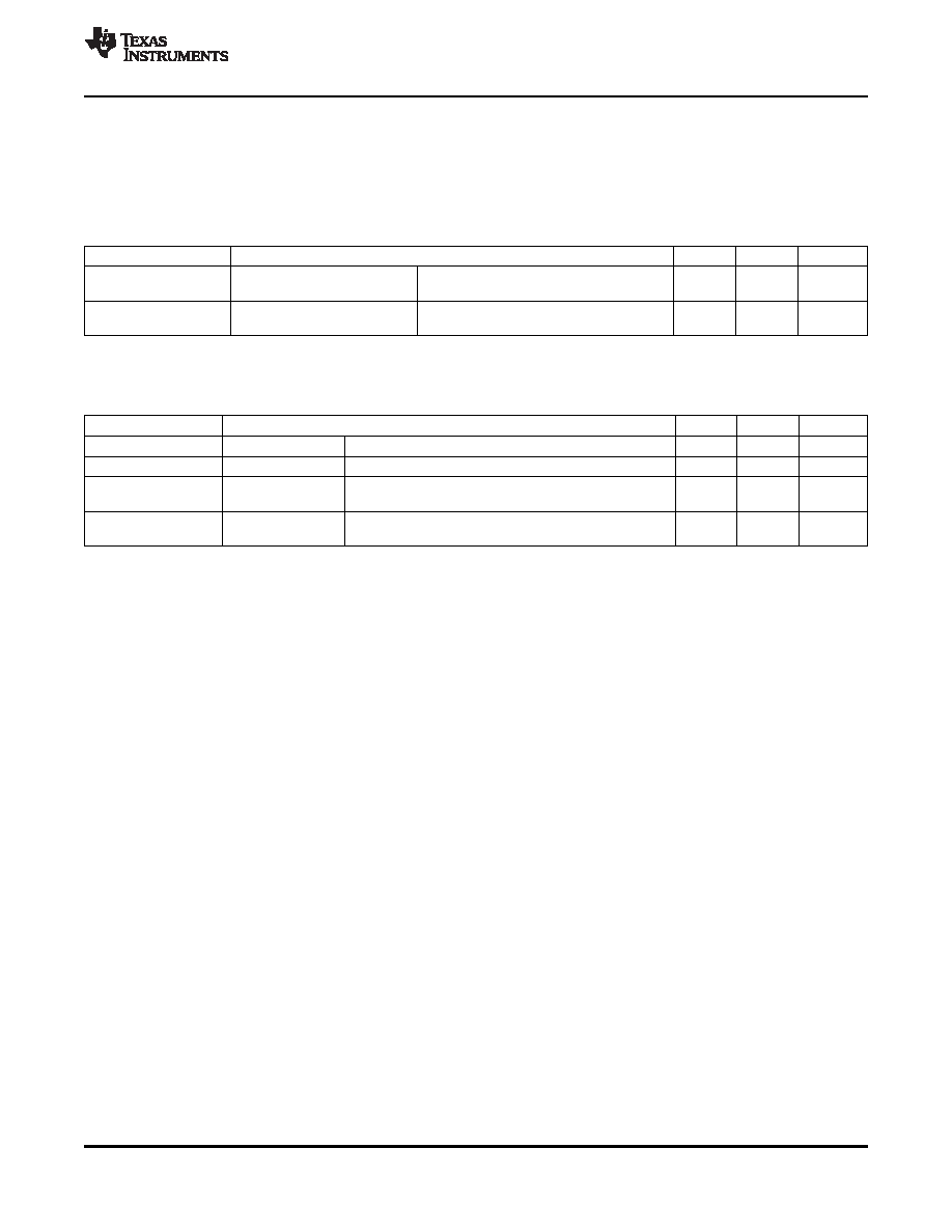
The timing requirements listed in Table 12-7 are valid on the following conditions of input slew and output
load:
Rise and fall time range of inputs (SYNC, DIN) is tR/tF = 1.0 ns/6.5 ns
Capacitance load range of outputs (CLK, SYNC, DOUT) is CLoad = 1 pF/30 pF
Table 12-7. TDM Interface Master Mode
—Timing Requirements
Notation
Parameter
Min
Max
Unit
T3
tsu(DIN-CLKH)
Setup time, TDM.DIN valid to TDM.CLK
25
ns
high
T4
th(DIN-CLKH)
Hold time, TDM.DIN valid from TDM.CLK
0
ns
high
Table 12-8 lists the switching characteristics of the TDM interface master mode.
Table 12-8. TDM Interface Master Mode
—Switching Characteristics
Notation
Parameter
Min
Max
Unit
T0
tc(CLK)
Cycle time, TDM.CLK (1)
1/64 * Fs
ns
T1
tw(CLK)
Pulse duration, TDM.CLK high or low(2)
0.45*P
0.55*P
ns
Delay time, TDM.CLK rising edge to TDM.SYNC
–10
10
ns
T2
td(CLKL-SYNC)
transition
Delay time, TDM.CLK rising edge to TDM.DOUT
–10
12
ns
T5
td(CLKL-DOUT)
transition
(1)
Fs = 8 to 48 kHz; 96 kHz for RX path only
(2)
P = TDM.CLK period
12.5 JTAG Interfaces
The TPS65920/TPS65930 device JTAG TAP controller handles standard IEEE JTAG interfaces. This
section describes the timing requirements for the tools used to test TPS65920/TPS65930 device power
management.
The JTAG/TAP module provides a JTAG interface according to IEEE Std1149.1a. This interface uses the
four I/O pins TMS, TCK, TDI, and TDO. The TMS, TCK, and TDI inputs contain a pullup device, which
makes their state high when they are not driven. The output TDO is a 3-state output, which is high
impedance except when data are shifted between TDI and TDO.
TCK is the test clock signal.
TMS is the test mode select signal.
TDI is the scan path input.
TDO is the scan path output.
TMS and TDO are multiplexed at the top level with the GPIO0 and GPIO1 pins. The dedicated external
TEST pin switches from functional mode (GPIO0/GPIO1) to JTAG mode (TMS/TDO). The JTAG
operations are controlled by a state-machine that follows the IEEE Std1149.1a state diagram. This
state-machine is reset by the TPS65920/TPS65930 internal power-on reset (POR). A test mode is
selected by writing a 6-bit word (instruction) into the instruction register and then accessing the related
data register.
Table 12-9 and Table 12-10 assume testing over the recommended operating conditions (see
Copyright
2008–2011, Texas Instruments Incorporated
Timing Requirements and Switching Characteristics
101
focus.ti.com: TPS65930/TPS65920
相關PDF資料 |
PDF描述 |
|---|---|
| TPS65920BZCH | SPECIALTY CONSUMER CIRCUIT, PBGA139 |
| TPS65930A2ZCHR | SPECIALTY CONSUMER CIRCUIT, PBGA139 |
| TPS65930A2ZCH | SPECIALTY CONSUMER CIRCUIT, PBGA139 |
| TPS65930BZCHR | SPECIALTY CONSUMER CIRCUIT, PBGA139 |
| TPS65930BZCH | SPECIALTY CONSUMER CIRCUIT, PBGA139 |
相關代理商/技術參數 |
參數描述 |
|---|---|
| TPS65921B1ZQZ | 功能描述:PMIC 解決方案 Integrated Power Mgmt IC RoHS:否 制造商:Texas Instruments 安裝風格:SMD/SMT 封裝 / 箱體:QFN-24 封裝:Reel |
| TPS65921B1ZQZR | 功能描述:PMIC 解決方案 Integrated Power Mgmt IC RoHS:否 制造商:Texas Instruments 安裝風格:SMD/SMT 封裝 / 箱體:QFN-24 封裝:Reel |
| TPS65921BZQZ | 功能描述:PMIC 解決方案 Int Power Mgmt IC RoHS:否 制造商:Texas Instruments 安裝風格:SMD/SMT 封裝 / 箱體:QFN-24 封裝:Reel |
| TPS65921BZQZR | 功能描述:PMIC 解決方案 Int Power Mgmt IC RoHS:否 制造商:Texas Instruments 安裝風格:SMD/SMT 封裝 / 箱體:QFN-24 封裝:Reel |
| TPS65930A2ZCH | 功能描述:PMIC 解決方案 Int Pwr Mgmt IC RoHS:否 制造商:Texas Instruments 安裝風格:SMD/SMT 封裝 / 箱體:QFN-24 封裝:Reel |
發布緊急采購,3分鐘左右您將得到回復。