- 您現在的位置:買賣IC網 > PDF目錄98305 > TUA6039-2 (INFINEON TECHNOLOGIES AG) 3-BAND, VIDEO TUNER, QCC48 PDF資料下載
參數資料
| 型號: | TUA6039-2 |
| 廠商: | INFINEON TECHNOLOGIES AG |
| 元件分類: | 調諧器 |
| 英文描述: | 3-BAND, VIDEO TUNER, QCC48 |
| 封裝: | GREEN, PLASTIC, VQFN-48 |
| 文件頁數: | 42/64頁 |
| 文件大小: | 1052K |
| 代理商: | TUA6039-2 |
第1頁第2頁第3頁第4頁第5頁第6頁第7頁第8頁第9頁第10頁第11頁第12頁第13頁第14頁第15頁第16頁第17頁第18頁第19頁第20頁第21頁第22頁第23頁第24頁第25頁第26頁第27頁第28頁第29頁第30頁第31頁第32頁第33頁第34頁第35頁第36頁第37頁第38頁第39頁第40頁第41頁當前第42頁第43頁第44頁第45頁第46頁第47頁第48頁第49頁第50頁第51頁第52頁第53頁第54頁第55頁第56頁第57頁第58頁第59頁第60頁第61頁第62頁第63頁第64頁
Data Sheet
47
Revision 2.6, 2007-08-20
TUA 6039-2, TUA 6039, TUA 6037
Reference
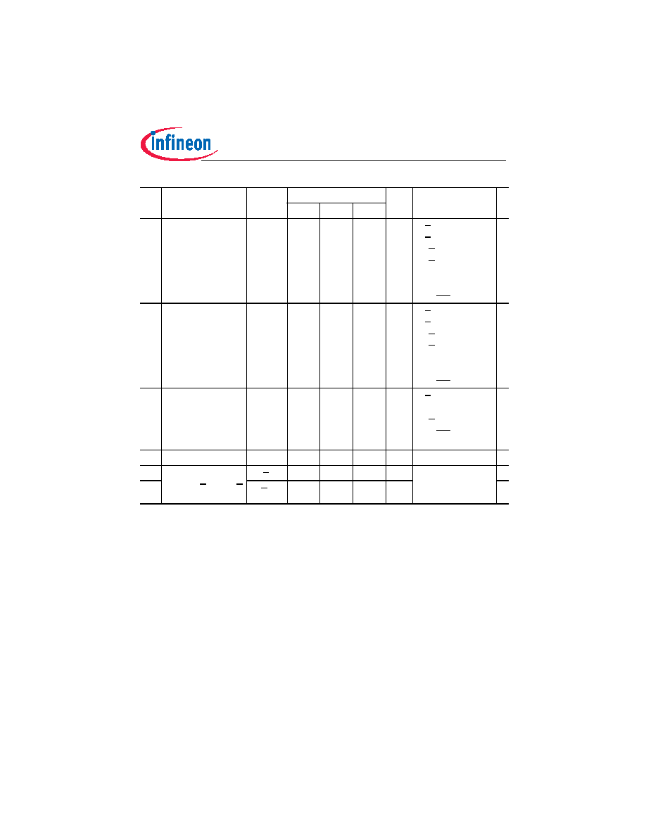
122. Intermodulation
C/IM3
-56
dBc
f
IF/IF1 = 37 MHz,
f
IF/IF2 = 38 MHz,
V
IF/IF1 = 90 dBV,
V
IF/IF2 = 90 dBV
R
LOAD ≥ 5k,
C
LOAD ≤ 10 pF,
V
OUT/OUT = 1 Vpp
123. Third order output
intercept point
OIP3
138
dBV f
IF/IF1 = 37 MHz,
f
IF/IF2 = 38 MHz,
V
IF/IF1 = 90 dBV,
V
IF/IF2 = 90 dBV
R
LOAD ≥ 5k,
C
LOAD ≤ 10 pF,
V
OUT/OUT = 1 Vpp
124. Signal to noise ratio SNR
43
dB
f
IF/IF = 36 MHz
(sine),
V
IF/IF = 60 dBV,
V
OUT/OUT = 1 Vpp,
BW = 8 MHz
125. Noise figure
9
dB
max. gain
126. Output impedance
Z
o = (RIF/IF + jωLIF/IF)
R
IF/IF
90
150
series equivalent
circuit at 36 MHz
see Section 5.4.8
127.
L
IF/IF
120
nH
1) Values are referred to the application given in Figure 9 and f
IF = 36 MHz, unless stated otherwise.
2) The RF frequency range is defined by the oscillator frequency range and the intermediate frequency (IF).
3) Local oscillator FM modulation resulting from I
2C communication is measured at the IF output using a
modulation analyzer with a peak to peak detector ((P
+ + P-) / 2) and a post detection filter 20 Hz - 100 kHz. The
I
2C messages are sent to the tuner in such a way that the tuner is addressed but the content of the PLL registers
are not altered. The refresh interval between each data set shall be 20 ms to 1 s.
4) (N+5) -1 MHz is defined as the input level of channel N+5, at frequency 1 MHz lower, causing 100 kHz FM
sidebands 30 dB below the wanted carrier.
5) Impedance measured with differential 2-port measurement at input or output. Input and output pins directly
connected to measurement equipment with 50
strip lines.
6) Limits are related to the tank circuit used in the application board (see Figure 9). Frequency bands may be
adjusted by the choice of external components.
7) For wide loop filter application (see Figure 11).
8) For narrow loop filter application (see Figure 10).
#
Parameter
1)
Symbol
Limit Values
Unit Test Conditions
■
min.
typ.
max.
相關PDF資料 |
PDF描述 |
|---|---|
| TUA6037 | 3-BAND, VIDEO TUNER, QCC48 |
| TUA6041-2 | 3-BAND, VIDEO TUNER, QCC48 |
| TUA6045-2 | 3-BAND, VIDEO TUNER, QCC48 |
| TVP5010CPFP | COLOR SIGNAL DECODER, PDSO80 |
| TVP5010PFP | COLOR SIGNAL DECODER, PQFP80 |
相關代理商/技術參數 |
參數描述 |
|---|---|
| TUA6039F-2 | 制造商:INFINEON 制造商全稱:Infineon Technologies AG 功能描述:3 Band Digital / Hybrid Tuner IC with integrated IF AGC amplifier |
| TUA6039F2XT | 制造商:Infineon Technologies AG 功能描述:Tuners PAL/NTSC 863.25MHz 48-Pin VQFN EP |
| TUA6039XT | 制造商:Infineon Technologies AG 功能描述:Tuners PAL/NTSC 863.25MHz 48-Pin VQFN |
| TUA6041 | 制造商:INFINEON 制造商全稱:Infineon Technologies AG 功能描述:Low Power 3-Band Digital TV / Portable Tuner IC with Digital Alignment |
| TUA60412XT | 制造商:Infineon Technologies AG 功能描述:Tuners TV 1.492GMHz 48-Pin VQFN |
發布緊急采購,3分鐘左右您將得到回復。