- 您現在的位置:買賣IC網 > PDF目錄382706 > U6225B 2.9 GHz PLL for SAT TV Receiver with Universal Bus PDF資料下載
參數資料
| 型號: | U6225B |
| 英文描述: | 2.9 GHz PLL for SAT TV Receiver with Universal Bus |
| 中文描述: | 2.9 GHz的鎖相環通用總線的衛星電視接收器 |
| 文件頁數: | 5/12頁 |
| 文件大小: | 166K |
| 代理商: | U6225B |
TELEFUNKEN Semiconductors
U6225B
Rev. A1: 25.10.1995
5 (12)
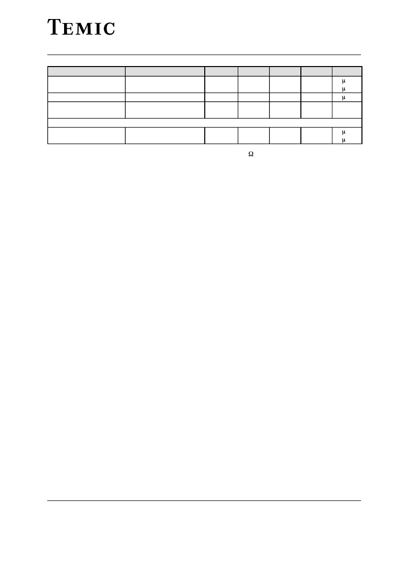
Unit
A
A
A
V
Max.
10
Typ.
Min.
Symbol
li ’H’
li ’L’
IL
VSDA ’L’
Test Conditions / Pins
VSCL ‘H’ = Vs Pin 4, 5
VSCL ‘L’ = 0 V Pin 4, 5
Vs = 0 V
ISDA ‘L’ = 2 mA,
Parameters
Input current
–10
Leakage current
Output voltage SDA (open
collector)
Address selection / Enable input
(AS, ENA)
Input current
Pin 4, 5
10
0.4
Pin 4
VAS ‘H’ = Vs
VAS ‘L’ = 0
Pin 10
Pin 10
liAS ’H’
liAS ’L’
–100
10
A
A
1)
RMS-voltage calculated from the measured available power on 50
2)
Tested with one switch active, the collector voltage may not exceed 6 V
Description
The U6225B-B is a single chip PLL designed for SAT-TV
receiver systems. It consists of a divide-by-16 prescaler
with an integrated preamplifier, a 15 bit programmable
divider, a crystal oscillator with a divide-by-512 refer-
ence divider, a phase/frequency detector together with a
charge-pump, which is driving the tuning amplifier. Only
one external transistor is required for varactor line driv-
ing. The device can be controlled via I
2
C-bus format or
the 3-wire-bus format. It detects automatically which bus
format is received, therefore there is no need of a bus
selection pin. In I
2
C-bus mode the device has 4 program-
mable addresses, programmed by applying a specific
input voltage to the address select input, enabling the use
of up to four synthesizers in a system. The same pin serves
in 3-wire-bus mode as the enable signal input. Five open
collector outputs for switching functions are included,
which are capable of sinking at least 10 mA. One of these
open collector outputs serves as Locksignal output in the
3-wire-bus mode.
Functional Description
The U6225B-B is programmed via 2-wire I
2
C bus or
3-wire bus depending on the received data format. The
three bus inputs pin 4, 5, 10 are used as SDA, SCL and
ADDRESS SELECT inputs in I
2
C-bus mode and as
DATA, CLOCK and ENABLE inputs in 3-wire bus mode.
The data includes the scaling factor SF (15 bit) and
switching output information. In I
2
C-bus mode there are
some additional functions for testing of the device in-
cluded.
Oscillator Frequency Calculation
fvco = 16 * SF * frefosc / 512
fvco: Locked frequency of voltage controlled
oscillator
SF:
Scaling factor of programmable
15-bit-divider
frefosc:
Reference oscillator frequency:
3.2 / 4 MHz crystal or external
reference frequency
The input amplifier together with a divide-by-16 pres-
caler gives an excellent sensitivity (see ‘Typical Prescaler
Input Sensitivity’). The input impedance is shown in the
diagram ‘Typical Input Impedance’. When a new divider
ratio according to the requested fvco is entered, the phase
detector and charge pump together with the tuning ampli-
fier adjusts the control voltage of the VCO until the output
signals of the programmable divider and the reference di-
vider are in frequency and phase locked. The reference
frequency may be provided by an external source capaci-
tively coupled into pin 2, or by using an on-board crystal
with an 18 pF capacitor in series. The crystal operates in
the series resonance mode. The reference divider division
ratio is fixed to 512. Therefore with a 4 MHz crystal the
comparison frequency is 7.8125 kHz, which gives
125 kHz steps for the VCO, or with a 3.2 MHz crystal re-
spectively 6.25 kHz comparison frequency and 100 kHz
VCO step size. In addition there are switching outputs
available for bandswitching and other purposes.
Application
A typical application is shown on page . All input / out-
put interface circuits are shown on page . Some special
features which are related to test- and alignment proce-
dures for tuner production are explained together within
the following bus mode description.
I
2
C-Bus Description
When the U6225B-B is controlled via 2-wire I
2
C-bus for-
mat, then data and clock signals are fed into the SDA and
SCL lines respectively. The table ’I
2
C-BUS DATA FOR-
MAT’ describes the format of the data and shows how to
select the device address by applying a voltage at pin 10.
When the correct address byte is received, the SDA line
is pulled low by the device during the acknowledge pe-
相關PDF資料 |
PDF描述 |
|---|---|
| U6225B-FPG3 | 2.9 GHz PLL for SAT TV Receiver with Universal Bus |
| U6229B | Low power dual operational amplifier |
| U6239B-AFSG3 | Low power dual operational amplifier |
| U6239B-CFPG3 | Analog Phase-Locked Loop |
| U6262B | Low power dual operational amplifier |
相關代理商/技術參數 |
參數描述 |
|---|---|
| U6225B-AFP | 制造商:未知廠家 制造商全稱:未知廠家 功能描述:Analog IC |
| U6225B-FPG3 | 制造商:TEMIC 制造商全稱:TEMIC Semiconductors 功能描述:2.9 GHz PLL for SAT TV Receiver with Universal Bus |
| U6229B | 制造商:TEMIC 制造商全稱:TEMIC Semiconductors 功能描述:DC/DC Converter - Power Supply 28 V |
| U6239B | 制造商:TEMIC 制造商全稱:TEMIC Semiconductors 功能描述:2.9 GHz PLL for SAT TV Tuner with UNi-Bus |
| U6239B-AFPG3 | 制造商:TEMIC 制造商全稱:TEMIC Semiconductors 功能描述:2.9 GHz PLL for SAT TV Tuner with UNi-Bus |
發布緊急采購,3分鐘左右您將得到回復。