- 您現在的位置:買賣IC網 > PDF目錄382716 > UAF42 UNIVERSAL ACTIVE FILTER PDF資料下載
參數資料
| 型號: | UAF42 |
| 英文描述: | UNIVERSAL ACTIVE FILTER |
| 中文描述: | 通用有源濾波器 |
| 文件頁數: | 13/14頁 |
| 文件大小: | 569K |
| 代理商: | UAF42 |
13
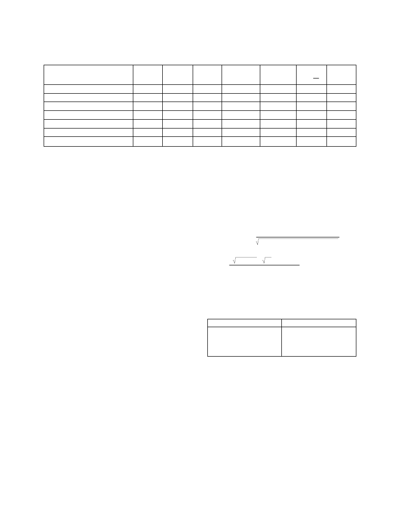
OP AMP SELECTION GUIDE (In Order of Increasing Slew Rate)
T
A
= 25
°
C, V
S
=
±
15V, specifications typ, unless otherwise noted, min/max specifications are for high-grade model.
BW
typ
(MHz)
FPR
(1)
typ
(kHz)
SR
typ
(V/
μ
s)
V
OS
max
(
μ
V)
V
OS
/dT
max
(
μ
V/
°
C)
NOISE
at 10kHz
(nV/
√
Hz)
OP AMP
MODEL
C
CM (3)
(pF)
OPA177
0.6
3
0.2
10
±
0.1
8
1
OPA27
8
30
1.9
25
±
0.6
2.7
1
OPA2107 dual
(2)
4.5
280
18
500
±
5
8
4
OPA602
(2)
6
500
35
250
±
2
12
3
OPA404 quad
(2)
6
500
35
1000
±
3 typ
12
3
OPA627
(2)
16
875
55
100
±
0.8
4.5
7
UAF42 aux amp
(2)
4
160
10
5000
±
3 typ
10
4
NOTES: (1) FPR is full power response at 20Vp-p as calculated from slew rate. (2) These op amps have FET inputs. (3) Common-mode input capacitance.
<ENTER>
. The program will toggle between
exact resis-
tors
and
standard 1% resistors
.
CAPACITOR SELECTION
Even-order filters above 10Hz normally will not require
external capacitors. Odd order filters require one external
capacitor to set the real pole in the LP or HP section.
Capacitor selection is very important for a high-performance
filter. Capacitor behavior can vary significantly from ideal,
introducing series resistance and inductance which limit Q.
Also, nonlinearity of capacitance vs voltage causes distor-
tion. The 1000pF capacitors in the UAF42 are high perfor-
mance types laser trimmed to 0.5%.
If external capacitors are required, the recommended capaci-
tor types are: NPO ceramic, silver mica, metallized polycar-
bonate; and, for temperatures up to 85
°
C, polypropylene or
polystyrene. Common ceramic capacitors with high dielec-
tric constants, such as “high-K” types should be avoided—
they can cause errors in filter circuits.
OP AMP SELECTION
Normally you can use the uncommitted fourth op amp in the
UAF42 to implement any necessary LP, HP, or gain stages.
If you must use additional op amps, it is important to choose
an op amp that can provide the necessary DC precision,
noise, distortion, and speed.
OP AMP SLEW RATE
The slew rate of the op amp must be greater than
π
V
OPP
BANDWIDTH
for adequate full-power response.
For example, operating at 100kHz with 20Vp-p output
requires an op amp slew rate of at least 6.3V/
μ
s. Burr-Brown
offers an excellent selection of op amps which can be used
for high performance active filter sections. The guide above
lists some good choices.
OP AMP BANDWIDTH
As a rule of thumb, in low-pass and band-pass applications,
op amp bandwidth should be at least 50 GAIN f
O
, where
GAIN = noise gain of the op amp configuration and
f
O
= filter f
–3dB
or f
CENTER
frequency.
In high-pass and band-reject (notch) applications, the re-
quired op amp bandwidth depends on the upper frequency of
interest. As with most active filters, high-pass filters de-
signed with the UAF42 turn into band-pass filters with an
upper roll-off determined by the op amp bandwidth. Error
due to op amp roll-off can be calculated as follows:
(
or
% = 100 1 –
1
(1 + f
2
(NGAIN)
2
/(UGBW)
2
)
)
f =
200 – % % UGBW
NGAIN (% – 100)
Where:
% = Percent gain error
NGAIN = Noise gain of op amp (V/V)
= GAIN of noninverting configuration
= 1 + |GAIN| of inverting configuration
UGBW = Unity-gain bandwidth of the op amp (Hz):
f = Frequency of interest (Hz)
GAIN ACCURACY (%)
f (NGAIN)/(UGBW)
–29.29
–10.00
–1.00
–0.10
–0.01
1.000
0.484
0.142
0.045
0.014
EXAMPLES OF MEASURED
UAF42 FILTER RESPONSE
Figures 17 and 18 show actual measured magnitude re-
sponse plots for 5th-order 5kHz Butterworth, 3dB Chebyshev,
–60dB Inverse Chebyshev and Bessel low-pass filters de-
signed with the program and implemented with UAF42s. As
can be seen, the initial roll-off of the Chebyshev filter is the
fastest and the roll-off of the Bessel filter is the slowest.
However, each of the 5th-order all-pole filters ultimately
rolls off at –N 20dB/decade, where N is the filter order
(–100dB/decade for a 5-pole filter).
The oscilloscope photographs (Figures 19-22) show the step
response for each filter. As expected, the Chebyshev filter
has the most ringing, while the Bessel has the least.
相關PDF資料 |
PDF描述 |
|---|---|
| UAF42AP | UNIVERSAL ACTIVE FILTER |
| UAF42AU | UNIVERSAL ACTIVE FILTER |
| UAG2 | 8-bit MCU for automotive with 16 to 60 Kbyte Flash, ADC, CSS, 5 timers, SPI, SCI, I2C interface |
| UART_AU1000_REV002 | 8-bit MCU for automotive with 16 to 60 Kbyte Flash, ADC, CSS, 5 timers, SPI, SCI, I2C interface |
| UAT05L | 8-bit MCU for automotive with 16 to 60 Kbyte Flash, ADC, CSS, 5 timers, SPI, SCI, I2C interface |
相關代理商/技術參數 |
參數描述 |
|---|---|
| UAF42 AP | 制造商:Texas Instruments 功能描述:IC FILTER UNIVERSAL ACTIVE |
| UAF42 AU | 制造商:Texas Instruments 功能描述:IC UNIVERSAL ACTIVE FILTER SMD 制造商:Texas Instruments 功能描述:IC, UNIVERSAL ACTIVE FILTER, SMD |
| UAF42AP | 功能描述:有源濾波器 Universal Active Filter RoHS:否 制造商:Maxim Integrated 通道數量:1 截止頻率:150 KHz 電源電壓-最大:11 V 電源電壓-最小:4.74 V 最大工作溫度:+ 85 C 安裝風格:Through Hole 封裝 / 箱體:PDIP N 封裝:Tube |
| UAF42AP | 制造商:Texas Instruments 功能描述:IC FILTER UNIVERSAL ACTIVE DIP14 |
| UAF42AP | 制造商:Texas Instruments 功能描述:IC FILTER UNIVERSAL ACTIVE DIP14 制造商:Texas Instruments 功能描述:IC, FILTER UNIVERSAL ACTIVE, DIP14 |
發布緊急采購,3分鐘左右您將得到回復。