- 您現在的位置:買賣IC網 > PDF目錄382720 > UCB1200 (NXP Semiconductors N.V.) Advanced modem/audio analog front-end PDF資料下載
參數資料
| 型號: | UCB1200 |
| 廠商: | NXP Semiconductors N.V. |
| 英文描述: | Advanced modem/audio analog front-end |
| 中文描述: | 先進的調制解調器/音頻模擬前端 |
| 文件頁數: | 50/54頁 |
| 文件大小: | 1052K |
| 代理商: | UCB1200 |
第1頁第2頁第3頁第4頁第5頁第6頁第7頁第8頁第9頁第10頁第11頁第12頁第13頁第14頁第15頁第16頁第17頁第18頁第19頁第20頁第21頁第22頁第23頁第24頁第25頁第26頁第27頁第28頁第29頁第30頁第31頁第32頁第33頁第34頁第35頁第36頁第37頁第38頁第39頁第40頁第41頁第42頁第43頁第44頁第45頁第46頁第47頁第48頁第49頁當前第50頁第51頁第52頁第53頁第54頁

1998 Jul 22
50
Philips Semiconductors
Product specification
Advanced modem/audio analog front-end
UCB1200
5
6
7
8 and 9
R/W
R/W
R/W
R/W
TSPX_GND
TSMY_GND
TSPY_GND
TSC_MODE[n]
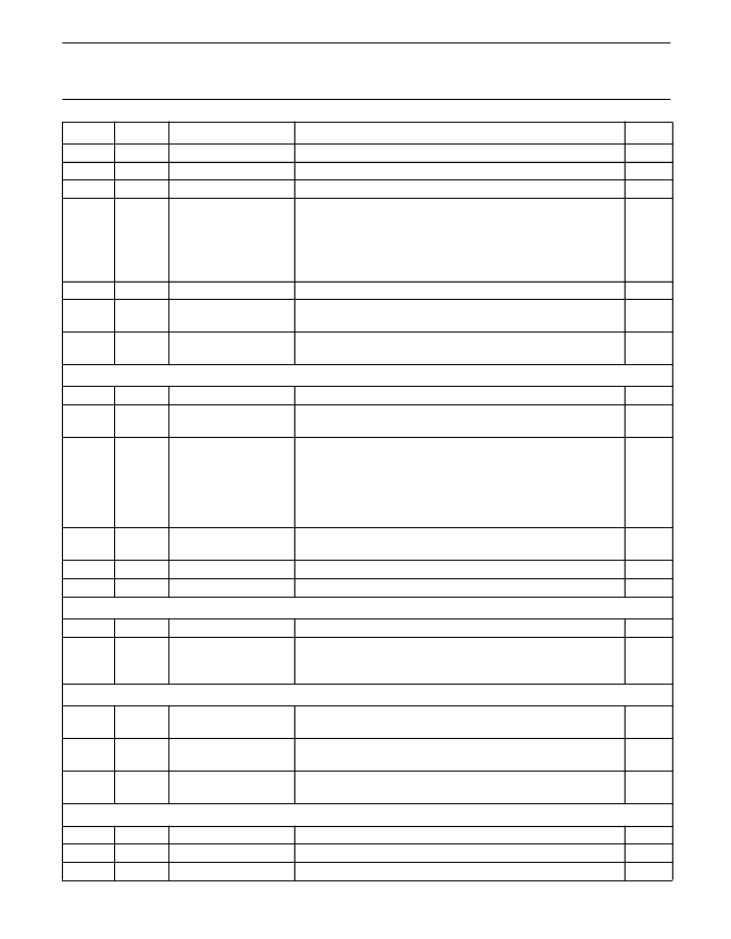
If ‘1’, the TSPX pin is grounded.
If ‘1’, the TSMY pin is grounded.
If ‘1’, the TSPY pin is grounded.
Touch screen operation mode:
00: interrupt mode
01: pressure measurement mode
1x: position measurement mode.
0
0
0
0
11
12
R/W
R
TSC_BIAS_ENA
TSPX_LOW
If ‘1’, the touch screen bias circuit is activated.
This bit returns the inverted state of the TSPX pin, ‘0’ is a high
voltage (pen up), ‘1’ is a low voltage (pen down).
This bit returns the inverted state of the TSMX pin, ‘0’ is a high
voltage (pen up), ‘1’ is a low voltage (pen down).
0
0
13
R
TSMX_LOW
0
Address 10: ADC control register
0
1
R/W
R/W
ADC_SYNC_ENA
VREFBYP_CON
If ‘1’, the ADC sync mode is activated.
If ‘1’, the internal reference voltage is connected to VREFBYP
(pin 16).
ADC input select:
000: TSPX
100: AD0
001: TSMX
101: AD1
010: TSPY
110: AD2
011: TSMY
110: AD3
If ‘1’, an external reference voltage has to be applied to
VREFBYP.
A ‘0’ to ‘1’ transition starts the ADC conversion sequence.
If ‘1’, the ADC circuit is activated.
2 to 4
R/W
ADC_INPUT[n]
0
5
R/W
EXT_REF_ENA
0
7
15
R/W
R/W
ADC_START
ADC_ENA
0
0
Address 11: ADC data register
5 to 14
15
R
R
ADC_DATA[n]
ADC_DAT_VAL
Returns the ADC result
Returns '0' if an ADC conversion is in progress. Returns '1' if
the ADC conversion is completed and the ADC data is stored
in the ADC_DATA[n] register.
0
0
Address 12: ID register
0 to 5
R
VERSION[n]
Returns 000100 for all the UCB1200 circuits meeting this
specification
Returns 000000 for all the UCB1200 circuits meeting this
specification
Returns 0001 for all the UCB1200 circuits meeting this
specification
0
6 to 11
R
DEVICE[n]
0
12 to 15 R
SUPPLIER[n]
0
Address 13: MODE register;
note 1
0
1
2 to 5
R/W
R/W
R/W
AUD_TEST
TEL_TEST
PROD_TEST_MODE
If ‘1’, the analog audio test mode is activated.
(2)
If ‘1’, the analog telecom test mode is activated.
(2)
These bits select the built-in production test modes.
(2)
0
0
0
BIT
MODE
SYMBOL
REMARK
RESET
相關PDF資料 |
PDF描述 |
|---|---|
| UCB1200BE | Advanced modem/audio analog front-end |
| UCB1300 | Advanced modem/audio analog front-end |
| UCB1300BE | Advanced modem/audio analog front-end |
| UCB1400BE | Audio codec with touch screen controller and power management monitor |
| UCB1400 | Audio codec with touch screen controller and power management monitor |
相關代理商/技術參數 |
參數描述 |
|---|---|
| UCB1200B | 制造商:未知廠家 制造商全稱:未知廠家 功能描述:UCB1200B |
| UCB1200BE | 制造商:PHILIPS 制造商全稱:NXP Semiconductors 功能描述:Advanced modem/audio analog front-end |
| UCB1300 | 制造商:PHILIPS 制造商全稱:NXP Semiconductors 功能描述:Advanced modem/audio analog front-end |
| UCB1300BE | 制造商:PHILIPS 制造商全稱:NXP Semiconductors 功能描述:Advanced modem/audio analog front-end |
| UCB1400 | 制造商:PHILIPS 制造商全稱:NXP Semiconductors 功能描述:Audio codec with touch screen controller and power management monitor |
發布緊急采購,3分鐘左右您將得到回復。