- 您現在的位置:買賣IC網 > PDF目錄376463 > XRT81L27 (Exar Corporation) Seven Channel E1 Line Interface Unit with Clock Recovery(7通道 E1線接口單元(帶時鐘恢復)) PDF資料下載
參數資料
| 型號: | XRT81L27 |
| 廠商: | Exar Corporation |
| 英文描述: | Seven Channel E1 Line Interface Unit with Clock Recovery(7通道 E1線接口單元(帶時鐘恢復)) |
| 中文描述: | 七通道E1線路接口單元的時鐘恢復(7通道素E1線接口單元(帶時鐘恢復)) |
| 文件頁數: | 1/28頁 |
| 文件大小: | 140K |
| 代理商: | XRT81L27 |
當前第1頁第2頁第3頁第4頁第5頁第6頁第7頁第8頁第9頁第10頁第11頁第12頁第13頁第14頁第15頁第16頁第17頁第18頁第19頁第20頁第21頁第22頁第23頁第24頁第25頁第26頁第27頁第28頁
Exar
Corporation 48720 Kato Road, Fremont CA, 94538
(510) 668-7000
FAX (510) 668-7017
www.exar.com
PRELIMINARY
XRT81L27
SEVEN CHANNEL E1 LINE INTERFACE UNIT WITH CLOCK RECOVERY
OCTOBER 2000
REV. P1.0.1
GENERAL DESCRIPTION
The XRT81L27 is an optimized seven-channel, ana-
log, 3.3V, line interface unit, fabricated using low
power CMOS technology. The device contains seven
independent E1 channels, including data and clock
recovery circuits. It is primarily targeted towards the
SDH multiplexers that accomodate TU12 Tributary
Unit Frames. Line cards in these units mutiplex 21 E1
channels into higher SDH rates. Devices with seven
E1 interfaces such as the XRT81L27 provide the
most efficient method of implementing 21-channel
line cards. Each channel performs the driver and re-
ceiver functions necessary to convert bipolar signals
to logical levels and vice versa.
The receiver input accepts transformer or capacitor
coupled signals, while the transmitter is coupled to
the line using a 1:2 step-up transformer. The same
transformer configuration can be used for both bal-
anced 120
and unbalanced 75
interfaces. The
Receiver Loss of Signal Detection is compliant to
G.775 and in Host Mode, the number of zeros re-
ceived before LOS is declared can be increased to
4096 bits. This feature provides the user with the
flexability to implement LOS specifications that re-
quire greater than G.775 requirements
FEATURES
Consists of Seven (7) Independent E1 (CEPT) Line
Interface Units (Transmitter and Receiver)
Generates Transmit Output Pulses that are Compli-
ant with the ITU-T G.703 Pulse Template Require-
ment for 2.048Mbps (E1) Rates
On-Chip Pulse Shaping for both 75
and 120
line
drivers
Receiver Can Either Be Transformer or Capacitive-
Coupled to the Line
Detects and Clears LOS (Loss of Signal) Per ITU-T
G.775
Compliant with the ITU-T G.823 Jitter Tolerance
Requirements
APPLICATIONS
lPDH Multiplexers
SDH Multiplexers
Digital Cross-Connect Systems
DECT (Digital European Cordless Telephone) Base
Stations
CSU/DSU Equipment
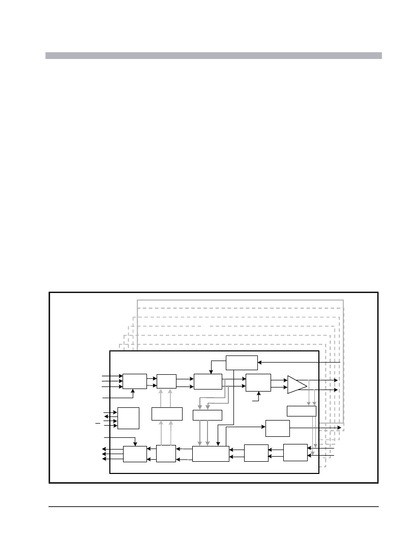
F
IGURE
1. B
LOCK
D
IAGRAM
Channe
l 1
Channel 2
Channel 3
Channel 4
Channel 5
Channel 6
TAOS
Channel 7
Timing
Generator
MClk
Encoder
MUX
Timing
Control
TX Pulse
Shaper
TClk
TPOS/TDATA
TNEG/CODE
TTIP
TRing
Remote
Loopback
TClkP
Decoder
Data & Timing
Recovery
Peak
Detector
Receive
Equalizer
Line
Driver
RClk
RPOS
RClkP
RTIP
RRing
LOS
Detect
LOS
Local
Loopback
Serial
Processor
Interface
SDI
SDO
SClk
CS
MUX
Analog
Loopback
RNEG/LCV
相關PDF資料 |
PDF描述 |
|---|---|
| XRT82D20 | Single Channel E1 Line Interface Unit(單通道E1線接口單元) |
| XRT82L24IV | QUAD E1 LINE TRANSCEIVER WITH CLOCK RECOVERY AND JITTER ATTENUATOR |
| XRT82L24 | Quad E1 Line Transceiver with Clock Recovery and Jitter Attenuator(四E1線收發器(帶時鐘恢復和振動衰減器)) |
| XRT82L34 | Quad T1/E1/J1 Line Transceiver with Clock Recovery and Jitter Attenuator(四 T1/E1/J1線收發器(帶時鐘恢復和振蕩衰減器)) |
| XRT82L38 | Octal E1/T1/J1 Line Transceiver with Clock Recovery and Jitter Attenuator(八 T1/E1/J1線收發器(帶時鐘恢復和振蕩衰減器)) |
相關代理商/技術參數 |
參數描述 |
|---|---|
| XRT81L27IV | 功能描述:外圍驅動器與原件 - PCI RoHS:否 制造商:PLX Technology 工作電源電壓: 最大工作溫度: 安裝風格:SMD/SMT 封裝 / 箱體:FCBGA-1156 封裝:Tray |
| XRT81L27IV-F | 功能描述:外圍驅動器與原件 - PCI RoHS:否 制造商:PLX Technology 工作電源電壓: 最大工作溫度: 安裝風格:SMD/SMT 封裝 / 箱體:FCBGA-1156 封裝:Tray |
| XR-T8205CP | 制造商:未知廠家 制造商全稱:未知廠家 功能描述:Telephone Ringer |
| XR-T8205P | 制造商:未知廠家 制造商全稱:未知廠家 功能描述:Telephone Ringer |
| XRT82D20 | 制造商:EXAR 制造商全稱:EXAR 功能描述:SINGLE CHANNEL E1 LINE INTERFACE UNIT |
發布緊急采購,3分鐘左右您將得到回復。