- 您現(xiàn)在的位置:買賣IC網 > Datasheet目錄49 > 30770 (Dresden Elektronik)SET DERFNODE FOR AVR HOUSING Datasheet資料下載
參數(shù)資料
| 型號: | 30770 |
| 廠商: | Dresden Elektronik |
| 文件頁數(shù): | 28/74頁 |
| 文件大小: | 2001K |
| 描述: | SET DERFNODE FOR AVR HOUSING |
| 標準包裝: | 1 |
第1頁第2頁第3頁第4頁第5頁第6頁第7頁第8頁第9頁第10頁第11頁第12頁第13頁第14頁第15頁第16頁第17頁第18頁第19頁第20頁第21頁第22頁第23頁第24頁第25頁第26頁第27頁當前第28頁第29頁第30頁第31頁第32頁第33頁第34頁第35頁第36頁第37頁第38頁第39頁第40頁第41頁第42頁第43頁第44頁第45頁第46頁第47頁第48頁第49頁第50頁第51頁第52頁第53頁第54頁第55頁第56頁第57頁第58頁第59頁第60頁第61頁第62頁第63頁第64頁第65頁第66頁第67頁第68頁第69頁第70頁第71頁第72頁第73頁第74頁
User Manual
Version 1.1
2011-07-15
deRFnode and deRFgateway
dresden elektronik
ingenieurtechnik gmbh
Enno-Heidebroek-Str. 12
12 7 Dr
n
rm n
Tel.: +49 351 31 85 00
Fax: +49 351 3 18 50 10
wireless@dresden-elektronik.de
www. r
n- l k r nik.
Page 28 of 56
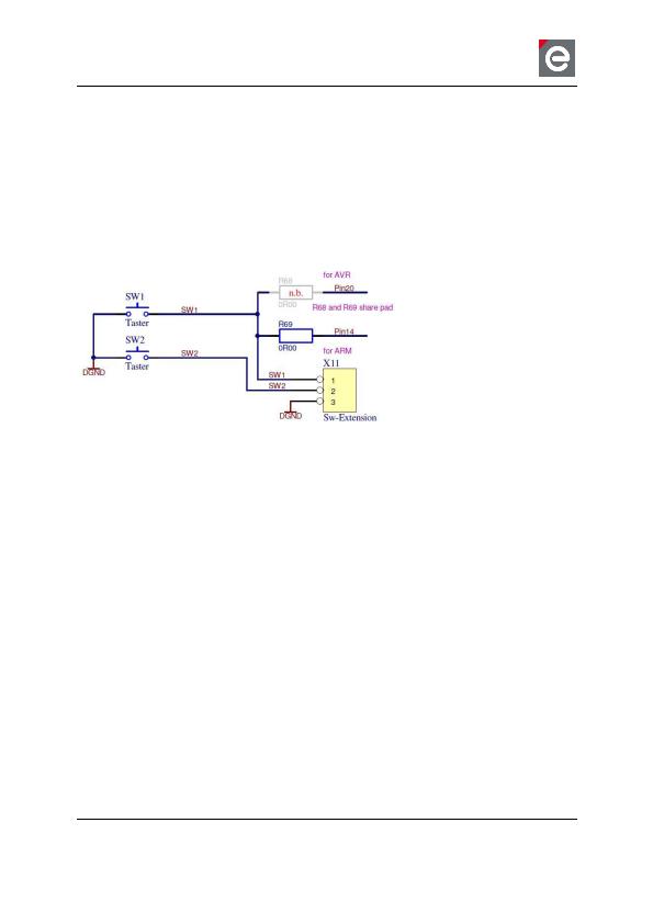
8.2.2. User buttons
The active-low buttons could be used for user defined inputs. The button [SW1] is controlled
by two different pins, which are connected by assembling the 0 ohms resistor [R68] or [R69].
The placement depends on the platform and is the result of the support of different radio
modules. The concerning pin of button 1 is used by the ARM based dresden elektronik radio
module to support the ethernet interface. The pin of button 2 can only be used, if the interrupt
feature of the acceleration sensor BMA150 is disabled.
Button 1 [SW1] on deRFnode:
Pin 20
Button 1 [SW1] on deRFgateway: Pin 14
Button 2 [SW2]:
Pin 29 by setting jumper [JP1] to pin 1 and 2.
Figure 17: User buttons
8.3. USB interface
Regarding the USB interface, the platforms deRFnode and deRFgateway come in two differ-
ent flavours. The deRFgateway USB interface can only be accessed over native USB of the
ARM based dresden elektronik radio modules. The deRFnode platform is offered in two vari-
ants. One with native USB for deRFarm7 radio module and another variant with an USB se-
rial converter for deRFmega128 radio modules.
相關PDF資料 |
PDF描述 |
|---|---|
| 3700BL15B100E | BALUN CERAMIC CHIP WIMAX 3.7GHZ |
| 4000BL14U100T | BALUN CERAMIC CHIP UWB 4GHZ |
| 4391-93 | ATTENUATOR BNC MALE/FMALE 93 OHM |
| 4432-T-B1 B 915 | KIT DEV TEST EZRADIOPRO SI4432 |
| 5250AT43A200E | ANTENNA CHIP 5.25GHZ WIFI |
相關代理商/技術參數(shù) |
參數(shù)描述 |
|---|---|
| 3077-0-00-01-00-00-33-0 | 制造商:Mill-Max Mfg Corp 功能描述: |
| 30770001 | 制造商: 功能描述: 制造商:undefined 功能描述: |
| 3077-0-00-15-00-00030 | 制造商:Mill-Max Mfg Corp 功能描述:3077 DOUBLE TAIL HEADER PIN |
| 307706 | 制造商:Weidmuller 功能描述:WBP-1/2IN NPT,STOPPING PLUG, -EA - Bulk |
| 307707 | 制造商:Weidmuller 功能描述:WBP-3/4IN NPT,STOPPING PLUG, -EA - Bulk |
發(fā)布緊急采購,3分鐘左右您將得到回復。