- 您現在的位置:買賣IC網 > Datasheet目錄49 > 30770 (Dresden Elektronik)SET DERFNODE FOR AVR HOUSING Datasheet資料下載
參數資料
| 型號: | 30770 |
| 廠商: | Dresden Elektronik |
| 文件頁數: | 7/74頁 |
| 文件大小: | 2001K |
| 描述: | SET DERFNODE FOR AVR HOUSING |
| 標準包裝: | 1 |
第1頁第2頁第3頁第4頁第5頁第6頁當前第7頁第8頁第9頁第10頁第11頁第12頁第13頁第14頁第15頁第16頁第17頁第18頁第19頁第20頁第21頁第22頁第23頁第24頁第25頁第26頁第27頁第28頁第29頁第30頁第31頁第32頁第33頁第34頁第35頁第36頁第37頁第38頁第39頁第40頁第41頁第42頁第43頁第44頁第45頁第46頁第47頁第48頁第49頁第50頁第51頁第52頁第53頁第54頁第55頁第56頁第57頁第58頁第59頁第60頁第61頁第62頁第63頁第64頁第65頁第66頁第67頁第68頁第69頁第70頁第71頁第72頁第73頁第74頁
User Manual
Version 1.1
2011-07-15
deRFnode and deRFgateway
dresden elektronik
ingenieurtechnik gmbh
Enno-Heidebroek-Str. 12
12 7 Dr
n
rm n
Tel.: +49 351 31 85 00
Fax: +49 351 3 18 50 10
wireless@dresden-elektronik.de
www. r
n- l k r nik.
Page 7 of 56
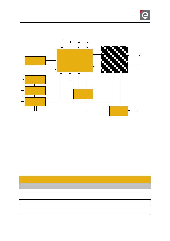
3.1. Block diagram
1)
optionally (only on deRFnode-series with AVR, otherwise included in MCU)
2)
on deRFgateway only
Figure 1: block diagram deRFnode/deRFgateway-series
3.2. Hardware selection table
From the electrical view, all deRF-radio modules may be combined with all deRFnode and
deRFgateway baseboards. However, not every peripheral available on the baseboard is us-
able or accessible by the radio module due to routing constraints respective missing MCU
features.
The portfolio of deRFnodes and deRFgateways will be added with new variants in the future.
All available platforms and variants are listed in Table 1.
Table 1: Available board and radio module combinations
ype code
ptimized for radio modules
l in v ri n
eRFnode-1TNP2-00N00
eRFarm7 series
eRFnode-2TNP2-00N00
eRFme a128 series
eRF atewa -1TNP2-00N00
eRFarm7 series
thernet
Radio Module
PIO
ADC
RQ
TAG
x
Voltage
Re ulator
CC
Serial Flash
USB
Transceiver
1)
SB
Reset
Supervisor
Ethernet
Transceiver
2)
Acceleration
Luminosity
n r
Temperature
n r
x
相關PDF資料 |
PDF描述 |
|---|---|
| 3700BL15B100E | BALUN CERAMIC CHIP WIMAX 3.7GHZ |
| 4000BL14U100T | BALUN CERAMIC CHIP UWB 4GHZ |
| 4391-93 | ATTENUATOR BNC MALE/FMALE 93 OHM |
| 4432-T-B1 B 915 | KIT DEV TEST EZRADIOPRO SI4432 |
| 5250AT43A200E | ANTENNA CHIP 5.25GHZ WIFI |
相關代理商/技術參數 |
參數描述 |
|---|---|
| 3077-0-00-01-00-00-33-0 | 制造商:Mill-Max Mfg Corp 功能描述: |
| 30770001 | 制造商: 功能描述: 制造商:undefined 功能描述: |
| 3077-0-00-15-00-00030 | 制造商:Mill-Max Mfg Corp 功能描述:3077 DOUBLE TAIL HEADER PIN |
| 307706 | 制造商:Weidmuller 功能描述:WBP-1/2IN NPT,STOPPING PLUG, -EA - Bulk |
| 307707 | 制造商:Weidmuller 功能描述:WBP-3/4IN NPT,STOPPING PLUG, -EA - Bulk |
發布緊急采購,3分鐘左右您將得到回復。