- 您現(xiàn)在的位置:買賣IC網 > PDF目錄68813 > 73S8014BN-ILR/F (MAXIM INTEGRATED PRODUCTS INC) SPECIALTY ANALOG CIRCUIT, PDSO20 PDF資料下載
參數(shù)資料
| 型號: | 73S8014BN-ILR/F |
| 廠商: | MAXIM INTEGRATED PRODUCTS INC |
| 元件分類: | 模擬信號調理 |
| 英文描述: | SPECIALTY ANALOG CIRCUIT, PDSO20 |
| 封裝: | ROHS COMPLIANT, SOP-20 |
| 文件頁數(shù): | 13/29頁 |
| 文件大小: | 345K |
| 代理商: | 73S8014BN-ILR/F |
第1頁第2頁第3頁第4頁第5頁第6頁第7頁第8頁第9頁第10頁第11頁第12頁當前第13頁第14頁第15頁第16頁第17頁第18頁第19頁第20頁第21頁第22頁第23頁第24頁第25頁第26頁第27頁第28頁第29頁
73S8014BN Data Sheet
DS_8014BN_057
20
Rev. 1.0
3.9
Fault Detection and
OFF
There are two different cases that the system controller can monitor the
OFF signal: to query regarding the card
presence and device readiness outside card sessions, or for fault detection during card sessions. The
OFF
interrupt output operates as follows:
As long as the card is not activated (
CMDVCC is always high), OFF informs the host about the card presence or
device readiness. When no card is inserted, the
OFF output is low. When a card is inserted, the OFF output is set
high after a 5ms debounce period. Upon card removal, there is no debounce on the PRES input as the
emergency deactivation must occur as soon as possible to prevent any potential card errors or data corruption.
The
OFF output goes low immediately upon detection of a logic-low on the PRES input, but the OFF output does
not bounce and remains low for at least 5ms.
In addition, when a card is present and the power-down mode is released, the
OFF output is taken low for about
5ms to indicate that the device is not ready. This time allows the crystal oscillator to start up and stabilize. When
CMDVCC is asserted low (card activation sequence requested from the host), low level on OFF means a fault has
been detected (e.g., card removal during card session, voltage fault, or overcurrent fault) that automatically
initiates a deactivation sequence.
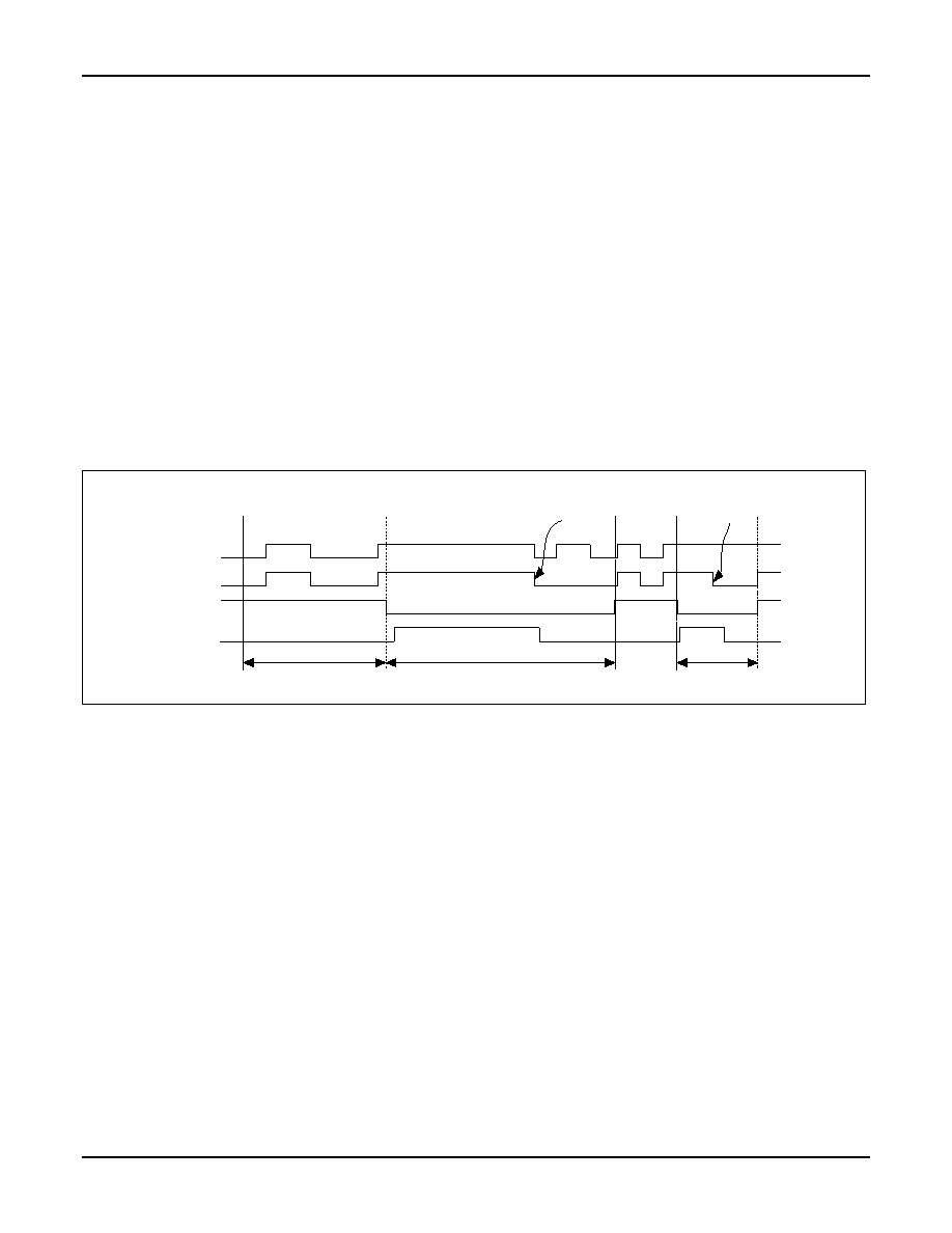
Figure 9 shows the timing diagram for the signals
CMDVCC, PRES, and OFF while the card is activated and
deactivated:
PRES
OFF
CMDVCC
VCC
outside card session
within card session
OFF is low by
card extracted
OFF is low by
any fault
within card
session
Figure 9: Timing Diagram—Management of the Interrupt Line
OFF
3.10 I/O, C4, and C8 Circuitry and Timing
The I/O, C4, and C8 are smart card data signals that operate identically, and I/OUC, C4UC, and C8UC are the
corresponding microcontroller interface signals. The I/O and I/OUC data signals are described henceforth. The
state of the I/O and I/OUC pins are low after power-on reset and goes high when the activation sequencer turns
on the I/O reception state. See the Activation Sequence section for details on when the I/O reception is enabled.
The state of I/OUC is high after power-on reset.
When the card is activated and the I/O reception state is turned on, the first I/O line on which a falling edge is
detected becomes the input I/O line and the other becomes the output I/O line. When the input I/O line rising edge
is detected, both I/O lines return to their neutral state.
Note: In certain situations and conditions, the I/O logic can get confused if the host and the card attempt to drive
the I/OUC and the I/O signal low at the same time. It should be noted that this is an illegal condition as all card
communication is initiated by the host with a command/response protocol. The next host command should not be
sent until a valid response has been completely received from the card. However, if this condition should occur,
the 73S8014BN could set both I/OUC and I/O as outputs where they are both driven low at the same time. When
either side drives their respective signal high, this mode should be released. However, if there is a series
resistance between the host and the 73S8014BN, there may not be enough drive to release this mode. If the
series resistance is greater than approximately 100
, this can cause this mode to become locked for the duration
of the card session. If the host detects this condition (I/OUC held low for more than 1 byte time), the card session
must be terminated and restarted.
相關PDF資料 |
PDF描述 |
|---|---|
| 73S8014BN-IL/F | SPECIALTY ANALOG CIRCUIT, PDSO20 |
| 73S8014RN-IL/F | SPECIALTY ANALOG CIRCUIT, PDSO20 |
| 73S8014RN-ILR/F | SPECIALTY ANALOG CIRCUIT, PDSO20 |
| 73S8023C-IM | SPECIALTY ANALOG CIRCUIT, QCC32 |
| 73S8023C-IM | SPECIALTY ANALOG CIRCUIT, QCC32 |
相關代理商/技術參數(shù) |
參數(shù)描述 |
|---|---|
| 73S8014R | 制造商:TERIDIAN 制造商全稱:TERIDIAN 功能描述:Smart Card Interface |
| 73S8014R-DB | 功能描述:界面開發(fā)工具 73S8014RRN/RT Demo Brd RoHS:否 制造商:Bourns 產品:Evaluation Boards 類型:RS-485 工具用于評估:ADM3485E 接口類型:RS-485 工作電源電壓:3.3 V |
| 73S8014R-IL/F | 功能描述:I2C 接口集成電路 Smart Card Interface Comp w/8024 RoHS:否 制造商:NXP Semiconductors 電源電壓-最大:5.5 V 電源電壓-最小:2.3 V 最大工作頻率:400 KHz 最大工作溫度:+ 85 C 封裝 / 箱體:TSSOP-16 |
| 73S8014R-IL/F1 | 功能描述:輸入/輸出控制器接口集成電路 RoHS:否 制造商:Silicon Labs 產品: 輸入/輸出端數(shù)量: 工作電源電壓: 最大工作溫度:+ 85 C 最小工作溫度:- 40 C 安裝風格:SMD/SMT 封裝 / 箱體:QFN-64 封裝:Tray |
| 73S8014R-IL/F2 | 功能描述:輸入/輸出控制器接口集成電路 Smart Card Interface Comp w/8024 RoHS:否 制造商:Silicon Labs 產品: 輸入/輸出端數(shù)量: 工作電源電壓: 最大工作溫度:+ 85 C 最小工作溫度:- 40 C 安裝風格:SMD/SMT 封裝 / 箱體:QFN-64 封裝:Tray |
發(fā)布緊急采購,3分鐘左右您將得到回復。