- 您現在的位置:買賣IC網 > PDF目錄373913 > AD7701SQ (ANALOG DEVICES INC) LC2MOS 16-Bit A/D Converter PDF資料下載
參數資料
| 型號: | AD7701SQ |
| 廠商: | ANALOG DEVICES INC |
| 元件分類: | ADC |
| 英文描述: | LC2MOS 16-Bit A/D Converter |
| 中文描述: | 1-CH 16-BIT DELTA-SIGMA ADC, SERIAL ACCESS, CDIP20 |
| 封裝: | CERDIP-20 |
| 文件頁數: | 15/16頁 |
| 文件大小: | 312K |
| 代理商: | AD7701SQ |
–15–
REV. D
AD7701
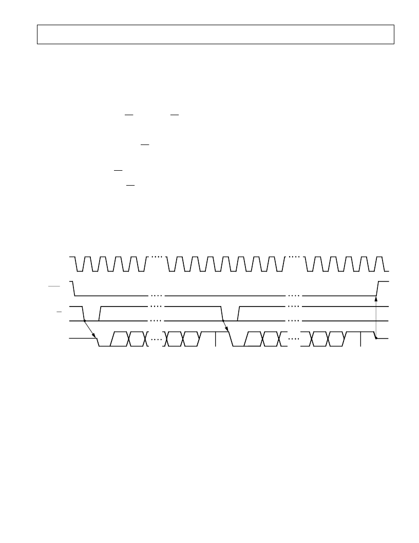
ASY NCHRONOUS COMMUNICAT IONS (AC) MODE
T he AC mode (MODE pin tied to –5 V) offers a UART -
compatible interface which allows the AD7701 to transmit data
asynchronously from remote locations. An external SCLK sets
the baud rate and data is transmitted in two bytes in UART -
compatible format. Using the AC mode, the AD7701 can be
interfaced direct to microprocessors with UART interfaces, such
as the 8051 and T MS70X 2.
Data transmission is initiated by
CS
going low. If
CS
is low on a
falling edge of SCLK , the AD7701 begins transmitting an 8-bit
data byte (DB8–DB15) with one start bit and two stop bits, as
in Figure 21. T he SDAT A output will then go three-state. T he
second byte is transmitted by bringing
CS
low again and DB0 to
DB7 are transmitted in the same format as the first byte.
UART baud rates are typically low compared to the AD7701’s
4 kHz output update rate. If
CS
is low and data is still being
transmitted when a new data word becomes available, the new
data will be ignored. However, if
CS
has been taken high
between bytes, when a new data word becomes available, the
AD7701 could update the output register before the second byte
is transmitted. In this case, the UART would receive the first
byte of the new word instead of the second byte of the old word.
When using the AC mode, care must obviously be taken to
ensure that this does not occur.
DIGIT AL NOISE AND OUT PUT LOADING
As mentioned earlier, the AD7701 divides its internal timing
into two distinct phases, analog sampling and settling and digital
computation. In the SSC mode, data is transmitted only during
the digital computation periods, to minimize the effects of
digital noise on analog performance. In the SEC and AC modes
data transmission is externally controlled, so this automatic
safeguard does not exist.
Whatever mode of operation is used, resistive and capacitive
loads on digital outputs should be minimized in order to reduce
crosstalk between analog and digital portions of the circuit. For
this reason connection to low-power CMOS logic such as one of
the 4000 series or 74C families is recommended.
It is especially important to minimize the load on SDAT A in the
AC mode, as transmission in this mode is inherently asynchro-
nous. In the SEC mode the AD7701 should be synchronized to
the digital system clock via CLK IN.
SCLK (I)
SDATA (O)
DB9
START
BIT
DB8
DB14
DB15
STOP
BIT
DB0
DB1
DB6
DB7
HI-Z
STOP
BIT
START
BIT
STOP
BIT
STOP
BIT
DRDY (O)
CS (I)
Figure 21. Timing Diagram for Asynchronous Communications Mode
相關PDF資料 |
PDF描述 |
|---|---|
| AD7701TQ | LC2MOS 16-Bit A/D Converter |
| AD7701 | LC2MOS 16-Bit A/D Converter |
| AD7703 | LC2MOS 20-Bit A/D Converter |
| AD7703AN | LC2MOS 20-Bit A/D Converter |
| AD7703AQ | LC2MOS 20-Bit A/D Converter |
相關代理商/技術參數 |
參數描述 |
|---|---|
| AD7701TQ | 制造商:AD 制造商全稱:Analog Devices 功能描述:LC2MOS 16-Bit A/D Converter |
| AD7703 | 制造商:AD 制造商全稱:Analog Devices 功能描述:LC2MOS 20-Bit A/D Converter |
| AD7703AN | 功能描述:IC ADC 20BIT LC2MOS 20-DIP RoHS:否 類別:集成電路 (IC) >> 數據采集 - 模數轉換器 系列:- 標準包裝:1 系列:- 位數:14 采樣率(每秒):83k 數據接口:串行,并聯 轉換器數目:1 功率耗散(最大):95mW 電壓電源:雙 ± 工作溫度:0°C ~ 70°C 安裝類型:通孔 封裝/外殼:28-DIP(0.600",15.24mm) 供應商設備封裝:28-PDIP 包裝:管件 輸入數目和類型:1 個單端,雙極 |
| AD7703ANZ | 功能描述:IC ADC 20BIT LC2MOS MONO 20DIP RoHS:是 類別:集成電路 (IC) >> 數據采集 - 模數轉換器 系列:- 其它有關文件:TSA1204 View All Specifications 標準包裝:1 系列:- 位數:12 采樣率(每秒):20M 數據接口:并聯 轉換器數目:2 功率耗散(最大):155mW 電壓電源:模擬和數字 工作溫度:-40°C ~ 85°C 安裝類型:表面貼裝 封裝/外殼:48-TQFP 供應商設備封裝:48-TQFP(7x7) 包裝:Digi-Reel® 輸入數目和類型:4 個單端,單極;2 個差分,單極 產品目錄頁面:1156 (CN2011-ZH PDF) 其它名稱:497-5435-6 |
| AD7703AQ | 制造商:Rochester Electronics LLC 功能描述:- Bulk |
發布緊急采購,3分鐘左右您將得到回復。