- 您現在的位置:買賣IC網 > PDF目錄373914 > AD7713* (Analog Devices, Inc.) LC2MOS Loop-Powered Signal Conditioning ADC PDF資料下載
參數資料
| 型號: | AD7713* |
| 廠商: | Analog Devices, Inc. |
| 英文描述: | LC2MOS Loop-Powered Signal Conditioning ADC |
| 中文描述: | LC2MOS回路供電ADC的信號調理 |
| 文件頁數: | 23/28頁 |
| 文件大小: | 516K |
第1頁第2頁第3頁第4頁第5頁第6頁第7頁第8頁第9頁第10頁第11頁第12頁第13頁第14頁第15頁第16頁第17頁第18頁第19頁第20頁第21頁第22頁當前第23頁第24頁第25頁第26頁第27頁第28頁
2
–23–
REV. C
AD7713
operations (where 24 bits of data are read into an 8-bit serial
register). A read operation to the control/calibration registers is
similar, but in this case the status of
DRDY
can be ignored. The
A0 line is brought low when the
RFS
line is brought low when
reading from the control register.
The flowchart also shows the bits being reversed after they have
been read in from the serial port. This depends on whether the
microprocessor expects the MSB of the word first or the LSB of
the word first. The AD7713 outputs the MSB first.
The flowchart for Figure 16 is for a single 24-bit write operation
to the AD7713 control or calibration registers. This shows data
being transferred from data memory to the accumulator before
being written to the serial buffer. Some microprocessor systems
will allow data to be written directly to the serial buffer from
data memory. The writing of data to the serial buffer from the
accumulator will generally consist of either two or three write
operations, depending on the size of the serial buffer.
The flowchart also shows the option of the bits being reversed
before being written to the serial buffer. This depends on
whether the first bit transmitted by the microprocessor is the
MSB or the LSB. The AD7713 expects the MSB as the first bit
in the data stream. In cases where the data is being read or be-
ing written in bytes and the data has to be reversed, the bits will
have to be reversed for every byte.
END
START
CONFIGURE &
INITIALIZE μC/μP
SERIAL PORT
x3
BRING
RFS
& A0 LOW
REVERSE ORDER OF
BITS
BRING
RFS
,
TFS
&
A0
HIGH
LOAD DATA FROM
ADDRESS TO
ACCUMULATOR
WRITE DATA FROM
ACCUMULATOR TO
SERIAL BUFFER
BRING
TFS
& A0 HIGH
Figure 16. Flowchart for Single Write Operation to the
AD7713
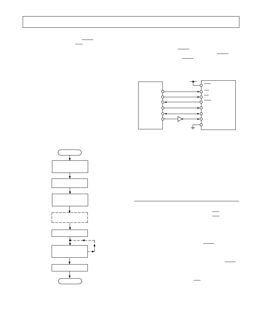
AD7713 to 8051 Interface
Figure 17 shows an interface between the AD7713 and the
8XC51 microcontroller. The AD7713 is configured for its exter-
nal clocking mode while the 8XC51 is configured in its Mode 0
serial interface mode. The
DRDY
line from the AD7713 is con-
nected to the Port P1.2 input of the 8XC51 so the
DRDY
line
is polled by the 8XC51. The
DRDY
line can be connected to
the INT1 input of the 8XC51 if an interrupt driven system is
preferred.
RFS
AD7713
SDATA
SCLK
TFS
A0
P1.0
P3.0
P3.1
P1.1
P1.2
MODE
DRDY
P1.3
SYNC
DV
DD
8XC51
Figure 17. AD7713 to 8XC51 Interface
Table V shows some typical 8XC51 code used for a single
24-bit read from the output register of the AD7713. Table V
shows some typical code for a single write operation to the con-
trol register of the AD7713. The 8XC51 outputs the LSB first
in a write operation while the AD7713 expects the MSB first, so
the data to be transmitted has to be rearranged before being
written to the output serial register. Similarly, the AD7713 out-
puts the MSB first during a read operation while the 8XC51
expects the LSB first. Therefore, the data which is read into the
serial buffer needs to be rearranged before the correct data word
from the AD7713 is available in the accumulator.
Table V. 8XC51 Code for Reading from the AD7713
MOV SCON,#00010001B;
MOV IE,#00010000B;
SETB 90H;
SETB 91H;
SETB 93H;
MOV R1,#003H;
Configure 8051 for MODE 0
Disable All Interrupts
Set P1.0, Used as
RFS
Set P1.1, Used as
TFS
Set P1.3, Used as A0
Sets Number of Bytes to Be Read in
A Read Operation
Start Address for Where Bytes Will
Be Loaded
Use P1.2 as
DRDY
MOV R0,#030H;
MOV R6,#004H;
WAIT:
NOP;
MOV A,P1;
ANL A,R6;
JZ READ;
SJMP WAIT;
READ:
CLR 90H;
CLR 98H;
POLL:
JB 98H, READ1
SJMP POLL
Read Port 1
Mask Out All Bits Except
DRDY
If Zero Read
Otherwise Keep Polling
Bring
RFS
Low
Clear Receive Flag
Tests Receive Interrupt Flag
continued on next page
相關PDF資料 |
PDF描述 |
|---|---|
| AD7713AN | LC2MOS Loop-Powered Signal Conditioning ADC |
| AD7713AQ | LC2MOS Loop-Powered Signal Conditioning ADC |
| AD7713AR | LC2MOS Loop-Powered Signal Conditioning ADC |
| AD7713SQ | LC2MOS Loop-Powered Signal Conditioning ADC |
| AD7713 | Loop-Powered Signal Conditioning ADC(循環驅動LC2MOS信號調節A/D轉換器) |
相關代理商/技術參數 |
參數描述 |
|---|---|
| AD7713AN | 功能描述:IC ADC 24BIT SIGMA-DELTA 24-DIP RoHS:否 類別:集成電路 (IC) >> 數據采集 - 模數轉換器 系列:- 產品培訓模塊:Lead (SnPb) Finish for COTS Obsolescence Mitigation Program 標準包裝:2,500 系列:- 位數:12 采樣率(每秒):3M 數據接口:- 轉換器數目:- 功率耗散(最大):- 電壓電源:- 工作溫度:- 安裝類型:表面貼裝 封裝/外殼:SOT-23-6 供應商設備封裝:SOT-23-6 包裝:帶卷 (TR) 輸入數目和類型:- |
| AD7713ANZ | 功能描述:IC ADC 24BIT SIGMA-DELTA 24-DIP RoHS:是 類別:集成電路 (IC) >> 數據采集 - 模數轉換器 系列:- 其它有關文件:TSA1204 View All Specifications 標準包裝:1 系列:- 位數:12 采樣率(每秒):20M 數據接口:并聯 轉換器數目:2 功率耗散(最大):155mW 電壓電源:模擬和數字 工作溫度:-40°C ~ 85°C 安裝類型:表面貼裝 封裝/外殼:48-TQFP 供應商設備封裝:48-TQFP(7x7) 包裝:Digi-Reel® 輸入數目和類型:4 個單端,單極;2 個差分,單極 產品目錄頁面:1156 (CN2011-ZH PDF) 其它名稱:497-5435-6 |
| AD7713AQ | 制造商:Rochester Electronics LLC 功能描述:24 BIT SIGMA DELTA ADC IC - Bulk |
| AD7713AR | 功能描述:IC ADC SIGNAL COND LC2MOS 24SOIC RoHS:否 類別:集成電路 (IC) >> 數據采集 - 模數轉換器 系列:- 產品培訓模塊:Lead (SnPb) Finish for COTS Obsolescence Mitigation Program 標準包裝:2,500 系列:- 位數:12 采樣率(每秒):3M 數據接口:- 轉換器數目:- 功率耗散(最大):- 電壓電源:- 工作溫度:- 安裝類型:表面貼裝 封裝/外殼:SOT-23-6 供應商設備封裝:SOT-23-6 包裝:帶卷 (TR) 輸入數目和類型:- |
發布緊急采購,3分鐘左右您將得到回復。