- 您現(xiàn)在的位置:買賣IC網(wǎng) > PDF目錄373916 > AD7760 (Analog Devices, Inc.) 2.5 MSPS, 20-Bit ADC PDF資料下載
參數(shù)資料
| 型號: | AD7760 |
| 廠商: | Analog Devices, Inc. |
| 英文描述: | 2.5 MSPS, 20-Bit ADC |
| 中文描述: | 2.5 MSPS的20位ADC |
| 文件頁數(shù): | 15/22頁 |
| 文件大小: | 868K |
| 代理商: | AD7760 |
Preliminary Technical Data
AD7760
DRIVING THE AD7760
The AD7760 has an on-chip differential amplifier. This
amplifier will operate with a supply voltage (AV
DD3
) from 3V to
5.5V. For a 4.096V reference, the supply voltage must be 5V.
Rev. PrN | Page 15 of 22
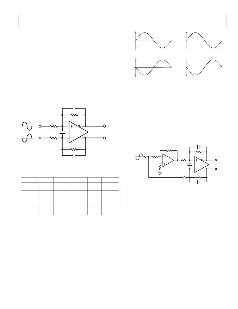
To achieve the specified performance in full power mode, the
differential amplifier should be configured as a first order anti-
alias filter as shown in Figure 16. Any additional filtering should
be carried out in previous stages using low noise, high-
performance op-amps such as the AD8021.
Suitable component values for the first order filter are listed in
Table 7. Using the first row as an example would yield a 10dB
attenuation at the first alias point of 19MHz.
Figure 16. Differential Amplifier Configuration
Table 7. Full Power Component Values
ODR
V
REF
R
IN
R
FB
C
S
C
FB
2.5MHz
4.096v
1k
655
5.6pF
33pF
2.5MHz
2.5v
TBD
TBD
TBD
TBD pF
48kHz
4.096v
TBD
TBD
TBD
TBD pF
48kHz
2.5v
TBD
TBD
TBD
TBD pF
Figure 17 shows the signal conditioning that occurs using the
circuit in Figure 16 with a ±2.5v input signal biased around
ground using the component values and conditions in the first
row of Table 7. The differential amplifier will always bias the
output signal to sit on the optimum common mode of V
REF
/2, in
this case 2.048V. The signal is also scaled to give the maximum
allowable voltage swing with this reference value. This is
calculated as 80% of V
REF
, i.e. 0.8 × 4.096V
≈
3.275V peak to
peak on each input.
(
) % (
* % (
(
) % (
* % (
) %(
%(
) %(
(
)
(
*
) %(
%(
) %(
Figure 17. Differential Amplifier Signal Conditioning
To obtain maximum performance from the AD7760, it is
advisable to drive the ADC with differential signals. However, it
is possible to drive the AD7760 with a single ended signal once
the common mode of the signal is within the range of +0.7V to
+2.1V with V
DD3
= 5V or +0.7 to +1.25V with V
DD3
= 3.3V. In
this case the on-chip differential amplifier can be used to
convert the signal from single-ended to differential before being
fed into the modulator inputs. Figure 18 shows how a bipolar
single-ended signal biased around ground can be used to drive
the AD7760 with the use of an external op-amp such as the
AD8021.
Figure 18. Single Ended to Differential Conversion
相關(guān)PDF資料 |
PDF描述 |
|---|---|
| AD7760BCP | 2.5 MSPS, 20-Bit ADC |
| AD7760BSV | 2.5 MSPS, 20-Bit ADC |
| AD7769 | LC2MOS Analog I/O Port |
| AD7769AN | LC2MOS Analog I/O Port |
| AD7769AP | LC2MOS Analog I/O Port |
相關(guān)代理商/技術(shù)參數(shù) |
參數(shù)描述 |
|---|---|
| AD7760BCP | 制造商:Analog Devices 功能描述:2.5MSPS 18/20 BIT SIGMA DELTA ADC - Bulk |
| AD7760BCPZ | 制造商:Analog Devices 功能描述:2.5MSPS 18/20 BIT SIGMA DELTA ADC - Bulk |
| AD7760BST | 制造商:Analog Devices 功能描述:2.5MSPS 18/20 BIT SIGMA DELTA ADC - Bulk |
| AD7760BSV | 制造商:AD 制造商全稱:Analog Devices 功能描述:2.5 MSPS, 20-Bit ADC |
| AD7760BSVZ | 功能描述:IC ADC 24BIT 2.5MSPS 64TQFP RoHS:是 類別:集成電路 (IC) >> 數(shù)據(jù)采集 - 模數(shù)轉(zhuǎn)換器 系列:- 其它有關(guān)文件:TSA1204 View All Specifications 標(biāo)準(zhǔn)包裝:1 系列:- 位數(shù):12 采樣率(每秒):20M 數(shù)據(jù)接口:并聯(lián) 轉(zhuǎn)換器數(shù)目:2 功率耗散(最大):155mW 電壓電源:模擬和數(shù)字 工作溫度:-40°C ~ 85°C 安裝類型:表面貼裝 封裝/外殼:48-TQFP 供應(yīng)商設(shè)備封裝:48-TQFP(7x7) 包裝:Digi-Reel® 輸入數(shù)目和類型:4 個單端,單極;2 個差分,單極 產(chǎn)品目錄頁面:1156 (CN2011-ZH PDF) 其它名稱:497-5435-6 |
發(fā)布緊急采購,3分鐘左右您將得到回復(fù)。