- 您現在的位置:買賣IC網 > PDF目錄373941 > AD8203YRZ-R7 (ANALOG DEVICES INC) High Common-Mode Voltage, Single-Supply Difference Amplifier PDF資料下載
參數資料
| 型號: | AD8203YRZ-R7 |
| 廠商: | ANALOG DEVICES INC |
| 元件分類: | 運動控制電子 |
| 英文描述: | High Common-Mode Voltage, Single-Supply Difference Amplifier |
| 中文描述: | OP-AMP, 1000 uV OFFSET-MAX, PDSO8 |
| 封裝: | LEAD FREE, MS-012AA, SOIC-8 |
| 文件頁數: | 15/20頁 |
| 文件大小: | 239K |
| 代理商: | AD8203YRZ-R7 |
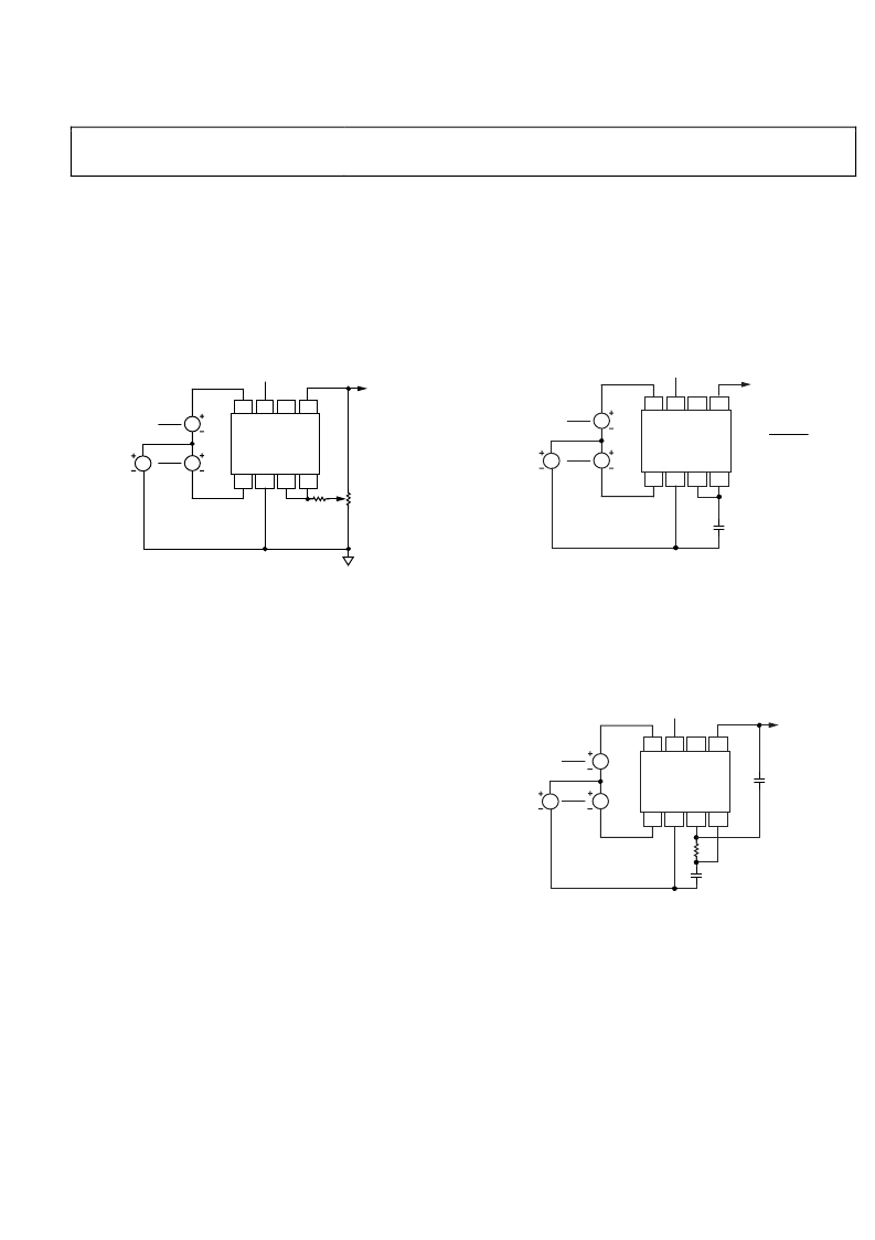
AD8203
GAIN TRIM
Figure 45 shows a method for incremental gain trimming by
using a trim potentiometer and external resistor R
Rev. B | Page 15 of 20
Low-pass filters can be implemented in several ways by using
the features provided by the AD8203. In the simplest case, a
single-pole filter (20 dB/decade) is formed when the output of
A1 is connected to the input of A2 via the internal 100 kΩ
resistor by strapping Pin 3, Pin 4, and a capacitor added from
this node to ground, as shown in
across the capacitor to lower the gain, the corner frequency
increases; it should be calculated using the parallel sum of the
resistor and 100 kΩ.
.
EXT
The following approximation is useful for small gain ranges:
Figure 46. If a resistor is added
Δ
G
≈ (10 MΩ/
R
EXT
)%
Thus, the adjustment range is ±2% for
R
EXT
= 5 MΩ; ±10% for
R
EXT
= 1 MΩ, and so on.
5V
V
CM
V
DIFF
2
V
DIFF
2
NC = NO CONNECT
C
GND
NC
–IN
+IN
A1
+V
S
A2
OUT
AD8203
0
OUTPUT
f
C
=
1
2
π
C10
5
C IN FARADS
5V
OUT
R
EXT
GAIN TRIM
20k
Ω
MIN
V
CM
V
DIFF
2
V
DIFF
2
NC = NO CONNECT
GND
NC
–IN
+IN
A1
+V
S
A2
OUT
AD8203
0
Figure 46. Single-Pole, Low-Pass Filter Using the Internal 100 kΩ Resistor
Figure 45. Incremental Gain Trim
If the gain is raised using a resistor, as shown in Figure 44, the
corner frequency is lowered by the same factor as the gain is
raised. Thus, using a resistor of 200 kΩ (for which the gain
would be doubled), the corner frequency is now 0.796 Hz μF
(0.039 μF for a 20 Hz corner frequency).
Internal Signal Overload Considerations
When configuring gain for values other than 14, the maximum
input voltage with respect to the supply voltage and ground
must be considered, since either the preamplifier or the output
buffer reaches its full-scale output (approximately V
S
0.2 V)
with large differential input voltages. The input of the AD8203
is limited to (V
amplifier, with its fixed gain of ×7, reaches its full-scale output
before the output buffer. For gains greater than 7, the swing at
the buffer output reaches its full scale first and limits the
AD8203 input to (V
S
0.2)/G, where G is the overall gain.
5V
V
CM
V
DIFF
2
V
DIFF
2
NC = NO CONNECT
C
GND
NC
–IN
+IN
A1
+V
S
A2
OUT
AD8203
0
OUT
C
255k
Ω
f
C
(Hz) = 1/C(
μ
F)
S
0.2)/7 for overall gains ≤ 7, since the pre-
LOW-PASS FILTERING
In many transducer applications, it is necessary to filter the
signal to remove spurious high frequency components, includ-
ing noise, or to extract the mean value of a fluctuating signal
with a peak-to-average ratio (PAR) greater than unity. For
example, a full-wave rectified sinusoid has a PAR of 1.57, a
raised cosine has a PAR of 2, and a half-wave sinusoid has a
PAR of 3.14. Signals having large spikes can have PARs of
10 or more.
Figure 47. 2-Pole, Low-Pass Filter
A 2-pole filter (with a roll-off of 40 dB/decade) can be implemented
using the connections shown in Figure 47. This is a Sallen-Key
form based on a ×2 amplifier. It is useful to remember that a 2-pole
filter with a corner frequency f
2
and a 1-pole filter with a corner at f
1
have the same attenuation at the frequency (f
at that frequency is 40 log (f
2
/f
1
), which is illustrated in Figure 48.
Using the standard resistor value shown and equal capacitors (see
Figure 47), the corner frequency is conveniently scaled at 1 Hz μF
(0.05 μF for a 20 Hz corner). A maximally flat response occurs
when the resistor is lowered to 196 kΩ and the scaling is then
1.145 Hz μF. The output offset is raised by approximately 5 mV
(equivalent to 250 μV at the input pins).
When implementing a filter, the PAR should be considered so
that the output of the AD8203 preamplifier (A1) does not clip
before A2, since this nonlinearity would be averaged and appear
as an error at the output. To avoid this error, both amplifiers
should be made to clip at the same time. This condition is
achieved when the PAR is no greater than the gain of the sec-
ond amplifier (2 for the default configuration). For example, if a
PAR of 5 is expected, the gain of A2 should be increased to 5.
22
/f
1
). The attenuation
相關PDF資料 |
PDF描述 |
|---|---|
| AD8203YRZ-RL | High Common-Mode Voltage, Single-Supply Difference Amplifier |
| AD8205YCSURF | Zero Drift, Digitally Programmable Instrumentation Amplifier; Package: LFCSP (4x4x.85mm, 2.10mm exposed pad); No of Pins: 16; Temperature Range: Industrial |
| AD8205YR-REEL | Single-Supply 42 V System Difference Amplifier |
| AD8205YR-REEL7 | 10 MHz, 20 V/µs, G = 1, 2, 4, 8 iCMOS® Programmable Gain Instrumentation Amplifier; Package: EVALUATION BOARDS; No of Pins: -; Temperature Range: Industrial |
| AD8205 | Single-Supply 42 V System Difference Amplifier |
相關代理商/技術參數 |
參數描述 |
|---|---|
| AD8203YRZ-RL | 功能描述:IC AMP DIFF 60KHZ 8SOIC RoHS:是 類別:集成電路 (IC) >> Linear - Amplifiers - Instrumentation 系列:- 標準包裝:2,500 系列:- 放大器類型:通用 電路數:1 輸出類型:滿擺幅 轉換速率:0.11 V/µs 增益帶寬積:350kHz -3db帶寬:- 電流 - 輸入偏壓:4nA 電壓 - 輸入偏移:20µV 電流 - 電源:260µA 電流 - 輸出 / 通道:20mA 電壓 - 電源,單路/雙路(±):2.7 V ~ 36 V,±1.35 V ~ 18 V 工作溫度:-40°C ~ 85°C 安裝類型:表面貼裝 封裝/外殼:8-SOIC(0.154",3.90mm 寬) 供應商設備封裝:8-SO 包裝:帶卷 (TR) |
| AD8205 | 制造商:AD 制造商全稱:Analog Devices 功能描述:Single-Supply 42 V System Difference Amplifier |
| AD8205AR | 制造商:Analog Devices 功能描述:- Bulk |
| AD8205WHRZ | 制造商:Analog Devices 功能描述:42VSNGLSUPPLYDIFFAMP - Rail/Tube 制造商:Analog Devices 功能描述:IC OPAMP DIFF 50KHZ 8SOIC 制造商:Analog Devices 功能描述:42V Sngl Supply Diff Amp |
| AD8205WHRZ-RL | 制造商:Analog Devices 功能描述:42VSNGLSUPPLYDIFFAMP - Tape and Reel 制造商:Analog Devices 功能描述:IC OPAMP DIFF 50KHZ 8SOIC 制造商:Analog Devices 功能描述:42V Sngl Supply Diff Amp |
發布緊急采購,3分鐘左右您將得到回復。