- 您現(xiàn)在的位置:買賣IC網(wǎng) > PDF目錄373943 > AD8313ARM-REEL (ANALOG DEVICES INC) 0.1 GHz-2.5 GHz, 70 dB Logarithmic Detector/Controller PDF資料下載
參數(shù)資料
| 型號: | AD8313ARM-REEL |
| 廠商: | ANALOG DEVICES INC |
| 元件分類: | 模擬信號調(diào)理 |
| 英文描述: | 0.1 GHz-2.5 GHz, 70 dB Logarithmic Detector/Controller |
| 中文描述: | SPECIALTY ANALOG CIRCUIT, PDSO8 |
| 封裝: | MO-187AA, MSOP-8 |
| 文件頁數(shù): | 11/16頁 |
| 文件大小: | 261K |
| 代理商: | AD8313ARM-REEL |
AD8313
–11–
REV. B
A positive input step on V
SET
(indicating a demand for in-
creased power from the PA) will drive V
OUT
towards ground.
This should be arranged to increase the gain of the PA. The
loop will settle when V
OUT
settles to a voltage that sets the input
power to the AD8313 to the dB equivalent of V
SET
.
Input Coupling
The signal may be coupled to the AD8313 in a variety of ways.
In all cases, there must not be a dc path from the input pins to
ground. Some of the possibilities include: dual input coupling
capacitors, a flux-linked transformer, a printed-circuit balun,
direct drive from a directional coupler, or a narrow-band imped-
ance matching network.
Figure 30 shows a simple broadband resistive match. A termina-
tion resistor of 53.6
combines with the internal input imped-
ance of the AD8313 to give an overall resistive input impedance
of approximately 50
. The termination resistor should prefer-
ably be placed directly across the input pins, INHI to INLO,
where it serves to lower the possible deleterious effects of dc
offset voltages on the low end of the dynamic range. At low
frequencies, this may not be quite as attractive, since it necessi-
tates the use of larger coupling capacitors. The two 680 pF
input coupling capacitors set the high-pass corner frequency of
the network at 9.4 MHz.
R
53.6
V
C1
680pF
C2
680pF
C
IN
R
IN
AD8313
50
V
50
V
SOURCE
Figure 30. A Simple Broadband Resistive Input Termination
The high pass corner frequency can be set higher according to
the equation:
f
C
dB
3
1
2
50
=
× ×
π
×
where:
C
C
C
C
C
=
×
+
1
1
2
2
In high frequency applications, the use of a transformer, balun
or matching network is advantageous. The impedance match-
ing characteristics of these networks provide what is essentially a
gain stage before the AD8313 that increases the device sensitiv-
ity. This gain effect is further explored in the following match-
ing example.
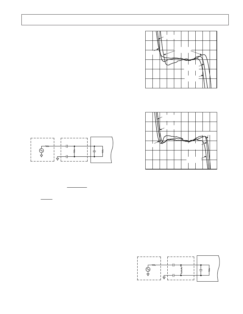
Figures 31 and 32 show device performance under these three
input conditions at 900 MHz and 1900 MHz.
While the 900 MHz case clearly shows the effect of input
matching by realigning the intercept as expected, little improve-
ment is seen at 1.9 GHz. Clearly, if no improvement in sensitiv-
ity is required, a simple 50
termination may be the best choice
for a given design based on ease of use and cost of components.
INPUT AMPLITUDE – dBm
–80
–70
–60
–50
–40
–30
–20
–10
3
2
1
0
–1
–2
–3
E
TERMINATED
DR = 66dB
–90
10
0
BALANCED
MATCHED
BALANCED
DR = 71dB
MATCHED
DR = 69dB
Figure 31. Comparison of Terminated, Matched and
Balanced Input Drive at 900 MHz
INPUT AMPLITUDE – dBm
–80
–70
–60
–50
–40
–30
–20
–10
0
3
2
1
0
–1
–2
–3
E
–90
10
TERMINATED
DR = 75dB
BALANCED
BALANCED
DR = 75dB
MATCHED
DR = 73dB
MATCHED
TERMINATED
Figure 32. Comparison of Terminated, Matched and
Balanced Input Drive at 1900 MHz
A Narrow-Band LC Matching Example at 100 MHz
While numerous software programs are available that allow the
values of matching components to be easily calculated, a clear
understanding of the calculations involved is valuable. A low
frequency (100 MHz) value has been used for this exercise
because of the deleterious board effects at higher frequencies.
RF layout simulation software is useful when board design at
higher frequencies is required.
A narrow-band LC match can be implemented either as a
series-inductance/shunt-capacitance or as a series-capacitance/
shunt-inductance. However, the concurrent requirement that the
AD8313 inputs, INHI and INLO, be ac-coupled, makes a
series-capacitance/shunt-inductance type match more appropri-
ate (see Figure 33).
L
MATCH
C1
C2
C
IN
R
IN
AD8313
50
V
50
V
SOURCE
Figure 33. Narrow-Band Reactive Match
相關PDF資料 |
PDF描述 |
|---|---|
| AD8313-EVAL | 0.1 GHz-2.5 GHz, 70 dB Logarithmic Detector/Controller |
| AD8313 | 0.1 GHz-2.5 GHz,70dB Logarithmic Detector/Controller(頻率為0.1 GHz-2.5 GHz,增益為70dB的對數(shù)檢測器/控制器) |
| AD8314ARM | 100 MHz-2500 MHz 45 dB RF Detector/Controller |
| AD8314ARM-REEL | 100 MHz-2500 MHz 45 dB RF Detector/Controller |
| AD8314ARM-REEL7 | 100 MHz-2500 MHz 45 dB RF Detector/Controller |
相關代理商/技術參數(shù) |
參數(shù)描述 |
|---|---|
| AD8313ARM-REEL7 | 功能描述:IC LOG DETECTOR/CTRLR 8-MSOP RoHS:否 類別:RF/IF 和 RFID >> RF 檢測器 系列:- 產(chǎn)品變化通告:Product Discontinuation 15/May/2006 標準包裝:3,000 系列:- 頻率:100MHz ~ 2GHz RF 型:手機,GSM,DCS,PCS 輸入范圍:- 精確度:- 電源電壓:2.7 V ~ 5.5 V 電流 - 電源:300µA 包裝:帶卷 (TR) 封裝/外殼:SC-74,SOT-457 其它名稱:NCS5000SNT1GOS |
| AD8313ARMZ | 功能描述:IC LOGARTIHMIC AMP 70DB 8-MSOP RoHS:是 類別:RF/IF 和 RFID >> RF 檢測器 系列:- 產(chǎn)品變化通告:Product Discontinuation 15/May/2006 標準包裝:3,000 系列:- 頻率:100MHz ~ 2GHz RF 型:手機,GSM,DCS,PCS 輸入范圍:- 精確度:- 電源電壓:2.7 V ~ 5.5 V 電流 - 電源:300µA 包裝:帶卷 (TR) 封裝/外殼:SC-74,SOT-457 其它名稱:NCS5000SNT1GOS |
| AD8313ARMZ | 制造商:Analog Devices 功能描述:IC DETECTOR/CONTROLLER 制造商:Analog Devices 功能描述:IC, DETECTOR/CONTROLLER |
| AD8313ARMZ | 制造商:Analog Devices 功能描述:IC, RF LOG DET, 100kHz to 2.5GHz, MSOP-8 |
| AD8313ARMZ-REEL | 功能描述:IC LOG DETECTOR/CTRLR 8MSOP RoHS:是 類別:RF/IF 和 RFID >> RF 檢測器 系列:- 產(chǎn)品變化通告:Product Discontinuation 15/May/2006 標準包裝:3,000 系列:- 頻率:100MHz ~ 2GHz RF 型:手機,GSM,DCS,PCS 輸入范圍:- 精確度:- 電源電壓:2.7 V ~ 5.5 V 電流 - 電源:300µA 包裝:帶卷 (TR) 封裝/外殼:SC-74,SOT-457 其它名稱:NCS5000SNT1GOS |
發(fā)布緊急采購,3分鐘左右您將得到回復。