- 您現在的位置:買賣IC網 > PDF目錄373943 > AD8322-EVAL (Analog Devices, Inc.) 5 V CATV Line Driver Coarse Step Output Power Control PDF資料下載
參數資料
| 型號: | AD8322-EVAL |
| 廠商: | Analog Devices, Inc. |
| 英文描述: | 5 V CATV Line Driver Coarse Step Output Power Control |
| 中文描述: | 5伏粗有線電視線路驅動器輸出功率控制步 |
| 文件頁數: | 10/16頁 |
| 文件大小: | 243K |
| 代理商: | AD8322-EVAL |
REV. 0
AD8322
–10–
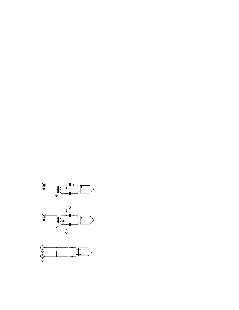
Single-Ended-to-Differential Input (Figure 8 Option 1)
Install the Mini-Circuits T1-6T-KK81 1:1 transformer in the T1
location of the evaluation board. Install 0
chip resistors in R12,
R13, and R17, and leave R14, R16, and R19 open. For 75
input impedance, install a 110
resistor in R7 located on the back
side of the evaluation board and leave R5 and R6 open. In this
configuration the input signal must be applied to the V
IN+
port of
the evaluation board from a single-ended 75
signal source. For
input impedances other than 75
, use the following equation
to compute the correct value for R7.
Desired Input Impedance
= R7 235
Single-Ended-to-Differential Input (Figure 8 Option 2)
Install the Mini-Circuits T1-6T-KK81 1:1 transformer in the T1
location of the evaluation board. Install 0
chip resistors in R12,
R13, R17, and R19, and leave R14 and R16 open. For 75
input
impedance, install 55
resistors in R5 and R6 located on the back
side of the evaluation board and leave R7 open. In this configu-
ration the input signal must be applied to the V
IN+
port of the
evaluation board from a single-ended 75
signal source. For
input impedances other than 75
, use the following equation
to compute the correct values for R5 and R6.
R5 = R6 = R, Desired Input Impedance
= 2
×
(R 117.5)
Differential Input (Figure 8 Option 3)
If a differential signal source is available, it may be applied directly
to both the V
IN+
and V
IN
–
input ports of the evaluation board. In
this case, install 0
chip resistors in R8, R14, R15, and R16, and
leave R12, R13, and R19 open. Referring to Figure 8 Option 3 and
the AD8322 evaluation board, a differential input impedance
of 150
can be achieved by installing a 432
resistor in R7,
leaving R5 and R6 open. If another input impedance is desired,
the following equation can be used to compute the correct
value for R7.
Desired Input Impedance
= R7 235
DIFF IN
T1
AD8322
R7
OPTION 1 DIFFERENTIAL INPUT TERMINATION
DIFF IN
T1
R5
R6
AD8322
OPTION 2 DIFFERENTIAL INPUT TERMINATION
R7
VIN+
AD8322
VIN
–
OPTION 3 DIFFERENTIAL INPUT TERMINATION
Figure 8. Differential Input Termination Options
Installing the Visual Basic Control Software
To install the
“
CABDRIVE_22
”
evaluation board control soft-
ware, first close all Windows applications and run
“
SETUP.EXE
”
located on Disk 1 of the AD8322 Evaluation Software. Follow
the on-screen instructions and insert Disk 2 when prompted to
do so. Enter the path of the directory into which the software
will be installed and select the button in the upper left corner to
complete the installation.
Running the Software
To invoke the control software, go to START -> PROGRAMS
-> CABDRIVE_22, or select the AD8322.EXE icon from the
directory containing the software.
Controlling the Gain/Attenuation of the AD8322
The slide bar controls the AD8322
’
s gain/attenuation, which is
displayed in dB and in V/V. Although the AD8322 is designed
for use at the eight gain codes described in the SPI Programming
and Gain Adjustment section, all of the intermediate codes are
included in the software. Code 0 is also included because of the
high isolation it provides. The gain code (i.e., position of the slide
bar) is displayed in decimal, binary, and hexadecimal (see
Figure 9).
POWER-UP AND POWER-DOWN
The
“
Power-Up
”
and
“
Power-Down
”
buttons select the mode of
operation of the AD8322 by controlling the logic level on the
asynchronous
PD
pin. The
“
Power-Up
”
button applies a Logic
1 to the
PD
pin putting the AD8322 in forward transmit mode.
The
“
Power-Down
”
button applies a Logic 0 to the
PD
pin select-
ing reverse mode, where the forward signal transmission is disabled
while a back termination of 75
is maintained.
Memory Section
The
“
MEMORY
”
section of the software provides a convenient
way to alternate between two gain settings. The
“
X->M1
”
but-
ton stores the current value of the gain slide bar into memory
while the
“
RM1
”
button recalls the stored value, returning the
gain slide bar to that level. The
“
X->M2
”
and
“
RM2
”
buttons
work in the same manner.
相關PDF資料 |
PDF描述 |
|---|---|
| AD8322ARU | 5 V CATV Line Driver Coarse Step Output Power Control |
| AD8322 | 5 V CATV Line Driver Coarse Step Output Power Control |
| AD8323ARU-REEL | 5 V CATV Line Driver Fine Step Output Power Control |
| AD8323ARU | 5 V CATV Line Driver Fine Step Output Power Control |
| AD8323 | 5 V CATV Line Driver Fine Step Output Power Control |
相關代理商/技術參數 |
參數描述 |
|---|---|
| AD8323 | 制造商:AD 制造商全稱:Analog Devices 功能描述:5 V CATV Line Driver Fine Step Output Power Control |
| AD8323ARU | 制造商:Analog Devices 功能描述:SP Amp Line Driver Amp Single 5.25V 28-Pin TSSOP Tube 制造商:Rochester Electronics LLC 功能描述:TSSOP FINE STEP +5V CATV LINE DRIVER - Bulk |
| AD8323ARU-REEL | 制造商:Analog Devices 功能描述:SP Amp Line Driver Amp Single 5.25V 28-Pin TSSOP T/R 制造商:Rochester Electronics LLC 功能描述:TSSOP FINE STEP +5V CATV LINE DRIVER - Tape and Reel |
| AD8323ARUZ | 制造商:Analog Devices 功能描述:SP Amp Line Driver Amp Single 5.25V 28-Pin TSSOP Tube 制造商:Rochester Electronics LLC 功能描述:TSSOP FINE STEP +5V CATV LINE DRIVER - Bulk |
| AD8323ARUZ-REEL | 制造商:Analog Devices 功能描述:SP Amp Line Driver Amp Single 5.25V 28-Pin TSSOP T/R 制造商:Rochester Electronics LLC 功能描述:TSSOP FINE STEP +5V CATV LINE DRIVER - Tape and Reel |
發布緊急采購,3分鐘左右您將得到回復。