- 您現(xiàn)在的位置:買賣IC網(wǎng) > PDF目錄373945 > AD8362ARUZ1 (Analog Devices, Inc.) 50 Hz to 2.7 GHz 60 dB TruPwr⑩ Detector PDF資料下載
參數(shù)資料
| 型號: | AD8362ARUZ1 |
| 廠商: | Analog Devices, Inc. |
| 英文描述: | 50 Hz to 2.7 GHz 60 dB TruPwr⑩ Detector |
| 中文描述: | 50赫茲到2.7 GHz 60分貝TruPwr⑩探測器 |
| 文件頁數(shù): | 22/36頁 |
| 文件大小: | 700K |
| 代理商: | AD8362ARUZ1 |
第1頁第2頁第3頁第4頁第5頁第6頁第7頁第8頁第9頁第10頁第11頁第12頁第13頁第14頁第15頁第16頁第17頁第18頁第19頁第20頁第21頁當前第22頁第23頁第24頁第25頁第26頁第27頁第28頁第29頁第30頁第31頁第32頁第33頁第34頁第35頁第36頁
AD8362
OPERATION IN MEASUREMENT MODES
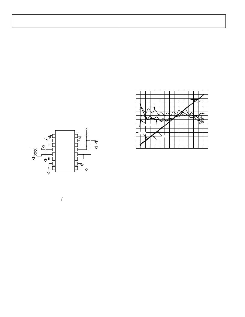
Figure 50 shows the general connections for operating the
AD8362 as an RF power detector, more correctly viewed
as an accurate measurement system. The full performance
potential of this part, particularly at very high frequencies
(above 500 MHz), is realized only when the input is presented
to the AD8362 in differential (balanced) form. In this example, a
flux-coupled transformer is used at the input. Having a 1:4
impedance ratio (1:2 turns ratio), the 200 differential input
resistance of the AD8362 becomes 50 at the input to the
transformer, whose outputs can be connected directly to INHI
and INLO. If a center-tapped transformer is used, connect the
tap to the DECL pins, which are biased to the same potential as
the inputs (~3.6 V). Over the 0.9 GHz to 2.2 GHz range, a
transmission line transformer (balun) may be used, as explained
later. (The evaluation board is supplied with a M/A-COM
ETC1.6-4-2-3, 0.5 GHz to 2.5 GHz, 4:1 balun.)
Rev. B | Page 22 of 36
16
15
14
13
12
11
10
9
1
2
3
4
5
6
7
8
COMM
CHPF
DECL
INHI
INLO
DECL
PWDN
COMM
ACOM
VREF
VTGT
VPOS
VOUT
VSET
ACOM
CLPF
1nF
V
RAIL-TO-RAIL
CONTROL OUTPUT
AD8362
SIGNAL INPUT
Z = 50
1nF
300pF
V
S
+5V nom, @ 24mA
0.1
μ
F
3.3
200
1nF
NC
1:4 Z-RATIO
(1:2 TURNS RATIO)
0
Figure 50. Connections for RF Power Measurement
The output in this mode of use is a continuous, decibel-scaled
voltage ranging from about 0.5 V to 3.5 V.
(
)
mV
P
P
VOUT
Z
IN
50
×
=
dB
(11)
The equivalent input power,
P
IN
, is expressed in dBm (decibels
above 1 mW) in a particular system impedance, which in this
case is 50 . The intercept,
P
Z
, is that input power for which
the back-extrapolated output crosses zero. Expressed as a
voltage, it is 0.447 mV rms (67 dBV, laser-calibrated at
100 MHz), corresponding to a
P
Z
of 60 dBm in 200 .
However, the 1:2 turns ratio of the transformer halves the
required input voltage, which moves the intercept down by
6 dB to 0.224 mV rms (73 dBV) at the transformer’s input.
Impedance mismatches and attenuation in the coupling
elements significantly affect the intercept position. This error
is stable over temperature and time, and thus can be removed
during calibration in a specific system. The logarithmic slope of
50 mV/dB varies only slightly with frequency; corrected values
for several common frequencies are provided in the
Specifications section.
LAW CONFORMANCE ERROR
In practice, the response deviates slightly from the ideal straight
line suggested by Equation 11. This deviation is called the law
conformance error. In defining the performance of high
accuracy measurement devices, it is customary to provide plots
of this error. In general terms, it is computed by extracting the
best straight line to the measured data using linear regression
over a substantial region of the dynamic range and under
clearly specified conditions.
INPUT AMPLITUDE (dBm)
0.2
0.8
1.1
1.4
1.7
2.0
2.3
2.9
3.5
0.5
3.8
–3.0
–1.5
–1.0
–0.5
0.5
1.0
1.5
2.0
2.5
–2.0
–2.5
3.0
2.6
3.2
–60 –55 –50 –45 –40 –35 –30 –25 –20 –15
–5
0
5
10 15
–10
0
–40°C
+25°C
+85°C
+25°C
+85°C
–40°C
0
Figure 51. Output Voltage and Law Conformance Error,
at T
A
= 40°C, +25°C, and +85°C
Figure 51 shows the output of the circuit of Figure 50 over the
full input range. The agreement with the ideal function (law
conformance) is also shown. This was determined by linear
regression on the data points over the central portion of the
transfer function (35 mV to 250 mV rms) for the 25°C data.
The error at +25°C, 40°C, and +85°C was then calculated by
subtracting the ideal output voltage at each input signal level
from the actual output and dividing this quantity by the mean
slope of the regression equation to provide a measurement of
the error in decibels (scaled on the right-hand axis of Figure 51).
The error curves generated in this way reveal not only the
deviations from the ideal transfer function at a nominal
temperature but also all of the additional errors caused by
temperature changes. Notice there is a small temperature
dependence in the intercept (the vertical position of the error
plots); this variation is within 0.5 dB at high powers.
Figure 51 further reveals that there is a periodic ripple in the
conformance curves. This is due to the interpolation technique
used to select the signals from the attenuator, not only at
discrete tap points, but anywhere in between, thus providing
continuous attenuation values. The selected signal is then
applied to the 3.5 GHz, 40 dB fixed gain amplifier in the
remaining stages of the AD8362’s VGA.
相關PDF資料 |
PDF描述 |
|---|---|
| AD8367ARU-REEL | 500 MHz, Linear-in-dB VGA with AGC Detector |
| AD8367-EVAL | RECTIFIER STANDARD SINGLE 1A 50V 50 30A-ifsm 5uA-ir 1V-vf DO-41 5K/REEL-13 |
| AD8367ARU-REEL-7 | 500 MHz, Linear-in-dB VGA with AGC Detector |
| AD8367 | 500 MHz, Linear-in-dB VGA with AGC Detector |
| AD8367ARU | 500 MHz, Linear-in-dB VGA with AGC Detector |
相關代理商/技術參數(shù) |
參數(shù)描述 |
|---|---|
| AD8362ARUZ-REEL7 | 功能描述:IC PWR DETECTOR 3.8GHZ 16-TSSOP RoHS:是 類別:RF/IF 和 RFID >> RF 檢測器 系列:- 產品變化通告:Product Discontinuation 15/May/2006 標準包裝:3,000 系列:- 頻率:100MHz ~ 2GHz RF 型:手機,GSM,DCS,PCS 輸入范圍:- 精確度:- 電源電壓:2.7 V ~ 5.5 V 電流 - 電源:300µA 包裝:帶卷 (TR) 封裝/外殼:SC-74,SOT-457 其它名稱:NCS5000SNT1GOS |
| AD8362ARUZ-REEL71 | 制造商:AD 制造商全稱:Analog Devices 功能描述:50 Hz to 2.7 GHz 60 dB TruPwr⑩ Detector |
| AD8362-EVAL | 制造商:Analog Devices 功能描述:RF DETECTOR, 50 HZ TO 2.7GHZ 60 DB TRUPWR DETECTOR - Bulk |
| AD8362-EVALZ | 功能描述:BOARD EVAL FOR AD8362 RoHS:是 類別:RF/IF 和 RFID >> RF 評估和開發(fā)套件,板 系列:TruePower™ 標準包裝:1 系列:- 類型:GPS 接收器 頻率:1575MHz 適用于相關產品:- 已供物品:模塊 其它名稱:SER3796 |
| AD8363 | 制造商:AD 制造商全稱:Analog Devices 功能描述:50 Hz to 6 GHz, 50 dB TruPwr? Detector |
發(fā)布緊急采購,3分鐘左右您將得到回復。