- 您現在的位置:買賣IC網 > PDF目錄373945 > AD8391AR-REEL (ANALOG DEVICES INC) xDSL Line Driver 3 V to 12 V with Power-Down PDF資料下載
參數資料
| 型號: | AD8391AR-REEL |
| 廠商: | ANALOG DEVICES INC |
| 元件分類: | 通用總線功能 |
| 英文描述: | xDSL Line Driver 3 V to 12 V with Power-Down |
| 中文描述: | DUAL LINE DRIVER, PDSO8 |
| 封裝: | PLASTIC, SOIC-8 |
| 文件頁數: | 13/20頁 |
| 文件大小: | 278K |
| 代理商: | AD8391AR-REEL |
REV. 0
AD8391
–13–
Receive Channel Considerations
A transformer used at the output of the differential line driver to
step up the differential output voltage to the line has the inverse
effect on signals received from the line. A voltage reduction or
attenuation equal to the inverse of the turns ratio is realized in the
receive channel of a typical bridge hybrid. The turns ratio of the
transformer may also be dictated by the ability of the receive
circuitry to resolve low-level signals in the noisy twisted pair tele-
phone plant. While higher turns ratio transformers boost transmit
signals to the appropriate level, they also effectively reduce the
received signal-to-noise ratio due to the reduction in the
received signal strength. Using a transformer with as low a turns
ratio as possible will limit degradation of the received signal.
The AD8022, a dual amplifier with typical RTI voltage noise of
only 2.5 nV/
√
Hz
and a low supply current of 4 mA/amplifier is
recommended for the receive channel. If power-down is required
for the receive amplifier, two AD8021 low-noise amplifiers can
be used instead.
DMT Modulation, Multitone Power Ratio (MTPR) and
Out-of-Band SFDR
ADSL systems rely on Discrete Multitone (DMT) modulation
to carry digital data over phone lines. DMT modulation appears
in the frequency domain as power contained in several individual
frequency subbands, sometimes referred to as tones or bins,
each of which are uniformly separated in frequency. A uniquely
encoded, Quadrature Amplitude Modulation (QAM) like signal
occurs at the center frequency of each subband or tone. See
Figure 7 for an example of a DMT waveform in the frequency
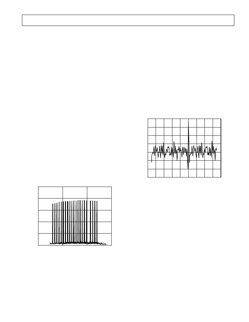
domain, and Figure 8 for a time domain waveform. Difficulties
will exist when decoding these subbands if a QAM signal from
one subband is corrupted by the QAM signal(s) from other
subbands regardless of whether the corruption comes from an
adjacent subband or harmonics of other subbands.
FREQUENCY
–
kHz
20
–
80
0
150
50
P
–
100
–
60
–
40
–
20
0
Figure 7. DMT Waveform in the Frequency Domain
Conventional methods of expressing the output signal integrity of
line drivers such as single-tone harmonic distortion or THD, two-
tone InterModulation Distortion (IMD) and third order intercept
(IP3) become significantly less meaningful when amplifiers are
required to process DMT and other heavily modulated waveforms.
A typical ADSL upstream DMT signal can contain as many as
27 carriers (subbands or tones) of QAM signals. Multitone Power
Ratio (MTPR) is the relative difference between the measured
power in a typical subband (at one tone or carrier) versus the
power at another subband specifically selected to contain no
QAM data. In other words, a selected subband (or tone) remains
open or void of intentional power (without a QAM signal) yielding
an empty frequency bin. MTPR, sometimes referred to as the
“
empty bin test,
”
is typically expressed in dBc, similar to express-
ing the relative difference between single-tone fundamentals and
second or third harmonic distortion components. Measurements
of MTPR are typically made on the line side or secondary side
of the transformer.
TIME
–
ms
4
–
0.25
V
0
3
1
0
2
–
0.2
–
1.5
–
1.0
–
0.05
0.05
1.0
1.5
0.2
–
3
–
2
–
1
Figure 8. DMT Signal in the Time Domain
TPC 21 and TPC 24 depict MTPR and SFDR versus transformer
turns respectively for a variety of line power ranging from 12 dBm to
14 dBm. As the turns ratio increases, the driver hybrid can deliver more
undistorted power to the load due to the high output current capa-
bility of the AD8391. Significant degradation of MTPR will occur
if the output transistors of the driver saturate, causing clipping at the
DMT voltage peaks. Driving DMT signals to such extremes not only
compromises
“
in-band
”
MTPR, but will also produce spurs that exist
outside of the frequency spectrum containing the transmitted signal.
“
Out-of-band
”
spurious-free dynamic range (SFDR) can be defined
as the relative difference in amplitude between these spurs and a tone
in one of the upstream bins. Compromising out-of-band SFDR is
the equivalent to increasing near-end crosstalk (NEXT). Regardless
of terminology, maintaining high out-of-band SFDR while reducing
NEXT will improve the overall performance of the modems connected
at either end of the twisted pair.
相關PDF資料 |
PDF描述 |
|---|---|
| AD8391AR-REEL7 | xDSL Line Driver 3 V to 12 V with Power-Down |
| AD8392ARE-REEL | Low Power, High Output Current, Quad Op Amp, Dual-Channel ADSL/ADSL2+ Line Driver |
| AD8392ARE-REEL7 | Low Power, High Output Current, Quad Op Amp, Dual-Channel ADSL/ADSL2+ Line Driver |
| AD8392 | Low Power, High Output Current, Quad Op Amp, Dual-Channel ADSL/ADSL2+ Line Driver |
| AD8392ACP-R2 | Low Power, High Output Current, Quad Op Amp, Dual-Channel ADSL/ADSL2+ Line Driver |
相關代理商/技術參數 |
參數描述 |
|---|---|
| AD8391AR-REEL7 | 功能描述:IC XDSL LINE DVR W/PWR DN 8-SOIC RoHS:否 類別:集成電路 (IC) >> 接口 - 驅動器,接收器,收發器 系列:- 標準包裝:1,140 系列:AU 類型:收發器 驅動器/接收器數:1/1 規程:CAN 電源電壓:5.3 V ~ 27 V 安裝類型:表面貼裝 封裝/外殼:14-SOIC(0.154",3.90mm 寬) 供應商設備封裝:14-SO 包裝:管件 其它名稱:935267940512AU5790D14AU5790D14-ND |
| AD8391ARZ | 制造商:Analog Devices 功能描述:SP Amp Line Driver Amp Dual ±6V/12V 8-Pin SOIC N Tube |
| AD8392 | 制造商:AD 制造商全稱:Analog Devices 功能描述:Low Power, High Output Current, Quad Op Amp, Dual-Channel ADSL/ADSL2+ Line Driver |
| AD8392A | 制造商:AD 制造商全稱:Analog Devices 功能描述:Low Power, High Output Current, Quad Op Amp, Dual-Channel ADSL/ADSL2+ Line Driver |
| AD8392AACPZ-R2 | 制造商:Analog Devices 功能描述:ADSL Driver Quad 32-Pin LFCSP EP T/R 制造商:Analog Devices 功能描述:ADSL DRVR QUAD 32LFCSP EP - Tape and Reel |
發布緊急采購,3分鐘左右您將得到回復。