- 您現在的位置:買賣IC網 > PDF目錄373999 > ADM1181 (Analog Devices, Inc.) 5V High-Speed RS-232 Transceivers with 0.1uF Capacitors PDF資料下載
參數資料
| 型號: | ADM1181 |
| 廠商: | Analog Devices, Inc. |
| 元件分類: | RS-232 |
| 英文描述: | 5V High-Speed RS-232 Transceivers with 0.1uF Capacitors |
| 中文描述: | 5V的高速RS - 232收發器與0.1uF電容 |
| 文件頁數: | 8/12頁 |
| 文件大小: | 163K |
| 代理商: | ADM1181 |
ADM202E/ADM1181A
–8–
REV. 0
T able I. IE C1000-4-2 Compliance Levels
Level
Contact Discharge
Air Discharge
1
2
3
4
2 kV
4 kV
6 kV
8 kV
2 kV
4 kV
8 kV
15 kV
T able II. ADM202E /ADM1181A E SD T est Results
E SD T est Method
I/O Pins
Other Pins
MIL-ST D-883B
IEC1000-4-2
Contact
Air
±
15 kV
±
3 kV
±
8 kV
±
15 kV
FAST T RANSIE NT BURST T E ST ING (IE C1000-4-4)
IEC1000-4-4 (previously 801-4) covers electrical fast-transient/
burst (EFT ) immunity. Electrical fast transients occur as a re-
sult of arcing contacts in switches and relays. T he tests simulate
the interference generated when for example a power relay dis-
connects an inductive load. A spark is generated due to the well
known back EMF effect. In fact the spark consists of a burst of
sparks as the relay contacts separate. T he voltage appearing on
the line therefore consists of a bust of extremely fast transient
impulses. A similar effect occurs when switching on fluorescent
lights.
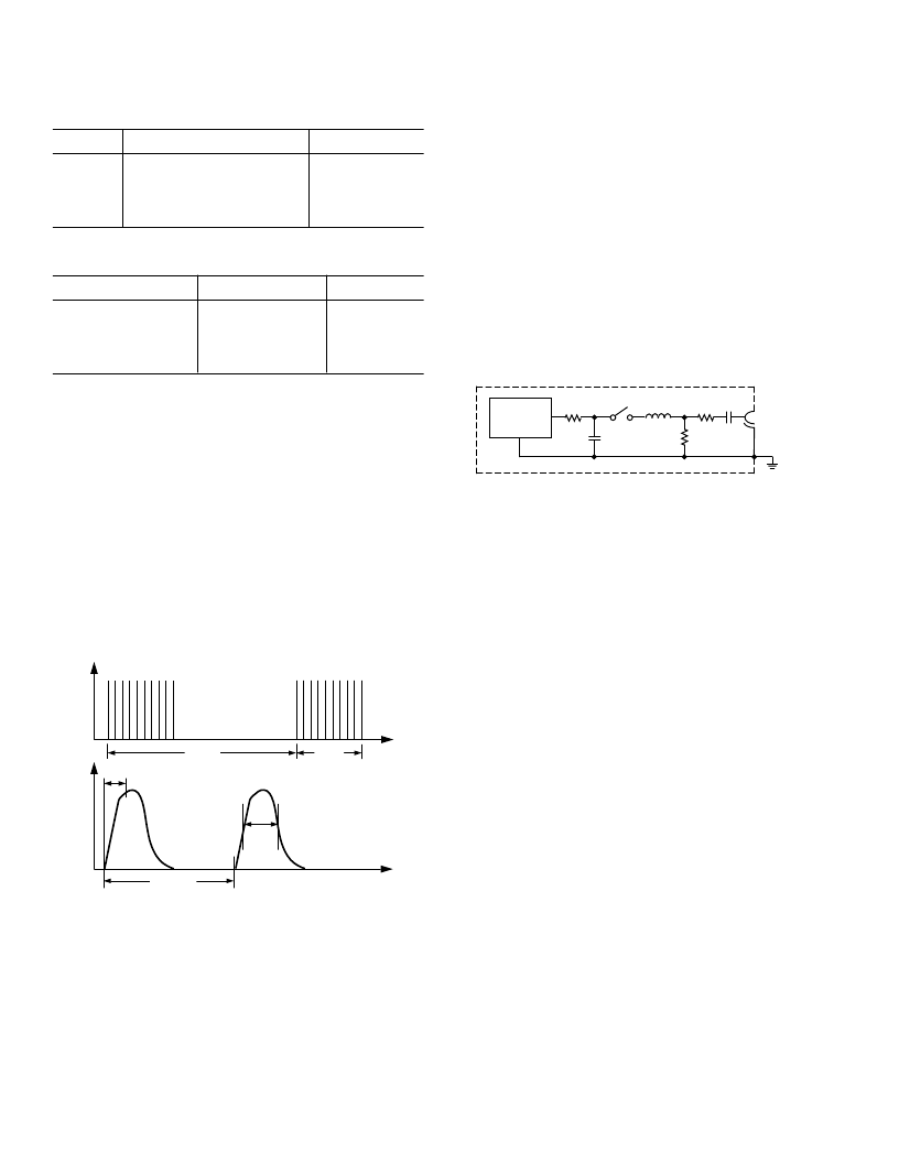
T he fast transient burst test defined in IEC1000-4-4 simulates
this arcing and its waveform is illustrated in Figure 11. It con-
sists of a burst of 2.5 kHz to 5 kHz transients repeating at
300 ms intervals. It is specified for both power and data lines.
300ms
15ms
t
V
5ns
0.2/0.4ms
50ns
V
t
Figure 15. IEC1000-4-4 Fast Transient Waveform
A simplified circuit diagram of the actual EFT generator is illus-
trated in Figure 16.
T he transients are coupled onto the signal lines using an EFT
coupling clamp. T he clamp is 1 m long and it completely sur-
rounds the cable providing maximum coupling capacitance
(50 pF to 200 pF typ) between the clamp and the cable. High
energy transients are capacitively coupled onto the signal lines.
Fast rise times (5 ns) as specified by the standard result in very
effective coupling. T his test is very severe since high voltages are
coupled onto the signal lines. T he repetitive transients can often
cause problems where single pulses don’t. Destructive latchup
may be induced due to the high energy content of the tran-
sients. Note that this stress is applied while the interface prod-
ucts are powered up and are transmitting data. T he EFT test
applies hundreds of pulses with higher energy than ESD. Worst
case transient current on an I/O line can be as high as 40 A.
R
C
R
M
C
C
HIGH
VOLTAGE
SOURCE
L
Z
S
C
D
50
OUTPUT
Figure 16. IEC1000-4-4 Fast Transient Generator
T est results are classified according to the following:
1. Normal performance within specification limits.
2. T emporary degradation or loss of performance that is
self-recoverable.
3. T emporary degradation or loss of function or performance
that requires operator intervention or system reset.
4. Degradation or loss of function that is not recoverable due
to damage.
T he ADM202E/ADM1181A have been tested under worst case
conditions using unshielded cables and meet Classification 2.
Data transmission during the transient condition is corrupted,
but it may be resumed immediately following the EFT event
without user intervention.
相關PDF資料 |
PDF描述 |
|---|---|
| ADM1181A | 5V High-Speed RS-232 Transceivers with 0.1uF Capacitors |
| ADM202EAN | 5V High-Speed RS-232 Transceivers with 0.1uF Capacitors |
| ADM202EARN | 5V High-Speed RS-232 Transceivers with 0.1uF Capacitors |
| ADM202EARU | 5V High-Speed RS-232 Transceivers with 0.1uF Capacitors |
| ADM1181AAN | 5V High-Speed RS-232 Transceivers with 0.1uF Capacitors |
相關代理商/技術參數 |
參數描述 |
|---|---|
| ADM1181A | 制造商:AD 制造商全稱:Analog Devices 功能描述:EMI/EMC Compliant, +-15 kV ESD Protected, RS-232 Line Drivers/Receivers |
| ADM1181AAN | 功能描述:IC TXRX RS-232 5V 15KV 16DIP RoHS:否 類別:集成電路 (IC) >> 接口 - 驅動器,接收器,收發器 系列:- 標準包裝:121 系列:- 類型:收發器 驅動器/接收器數:1/1 規程:RS422,RS485 電源電壓:3 V ~ 3.6 V 安裝類型:表面貼裝 封裝/外殼:10-WFDFN 裸露焊盤 供應商設備封裝:10-DFN(3x3) 包裝:管件 |
| ADM1181AANZ | 功能描述:IC TXRX RS-232 5V 15KV 16-DIP RoHS:是 類別:集成電路 (IC) >> 接口 - 驅動器,接收器,收發器 系列:- 標準包裝:121 系列:- 類型:收發器 驅動器/接收器數:1/1 規程:RS422,RS485 電源電壓:3 V ~ 3.6 V 安裝類型:表面貼裝 封裝/外殼:10-WFDFN 裸露焊盤 供應商設備封裝:10-DFN(3x3) 包裝:管件 |
| ADM1181AARW | 功能描述:IC TXRX RS-232 5V 15KV 16SOIC RoHS:否 類別:集成電路 (IC) >> 接口 - 驅動器,接收器,收發器 系列:- 標準包裝:121 系列:- 類型:收發器 驅動器/接收器數:1/1 規程:RS422,RS485 電源電壓:3 V ~ 3.6 V 安裝類型:表面貼裝 封裝/外殼:10-WFDFN 裸露焊盤 供應商設備封裝:10-DFN(3x3) 包裝:管件 |
| ADM1181AARW-REEL | 制造商:Analog Devices 功能描述:Dual Transmitter/Receiver RS-232 16-Pin SOIC W T/R |
發布緊急采購,3分鐘左右您將得到回復。