- 您現在的位置:買賣IC網 > PDF目錄374004 > ADM489AR (ANALOG DEVICES INC) Full-Duplex, Low Power, Slew Rate Limited, EIA RS-485 Transceivers PDF資料下載
參數資料
| 型號: | ADM489AR |
| 廠商: | ANALOG DEVICES INC |
| 元件分類: | 通用總線功能 |
| 英文描述: | Full-Duplex, Low Power, Slew Rate Limited, EIA RS-485 Transceivers |
| 中文描述: | LINE TRANSCEIVER, PDSO14 |
| 封裝: | MS-012AB, SOIC-14 |
| 文件頁數: | 11/12頁 |
| 文件大小: | 212K |
| 代理商: | ADM489AR |
ADM488/ADM489
–11–
REV. 0
T able V. Comparison of RS-422 and RS-485 Interface Standards
Specification
RS-422
RS-485
T ransmission T ype
Maximum Data Rate
Maximum Cable Length
Minimum Driver Output Voltage
Driver Load Impedance
Receiver Input Resistance
Receiver Input Sensitivity
Receiver Input Voltage Range
Number of Drivers/Receivers Per Line
Differential
10 MB/s
4000 ft.
±
2 V
100
4 k
min
±
200 mV
–7 V to +7 V
1/10
Differential
10 MB/s
4000 ft.
±
1.5 V
54
12 k
min
±
200 mV
–7 V to +12 V
32/32
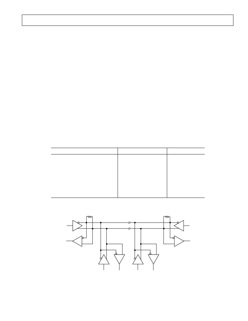
D
R
D
R
D
D
R
R
RT
RT
Figure 25. Typical RS-485 Network
APPLICAT IONS INFORMAT ION
Differential Data T ransmission
Differential data transmission is used to reliably transmit data
at high rates over long distances and through noisy environ-
ments. Differential transmission nullifies the effects of ground
shifts and noise signals, which appear as common-mode volt-
ages on the line. T wo main standards are approved by the
Electronics Industries Association (EIA), which specify the
electrical characteristics of transceivers used in differential
data transmission.
T he RS-422 standard specifies data rates up to 10 MBaud and
line lengths up to 4000 ft. A single driver can drive a transmis-
sion line with up to 10 receivers.
In order to cater to true multipoint communications, the RS-
485 standard was defined. T his standard meets or exceeds all
the requirements of RS-422 and also allows for up to 32 drivers
and 32 receivers to be connected to a single bus. An extended
common-mode range of –7 V to +12 V is defined. T he most
significant difference between RS-422 and RS-485 is the fact
that the drivers may be disabled thereby allowing more than
one (32, in fact) to be connected to a single line. Only one
driver should be enabled at a time but the RS-485 standard
contains additional specifications to guarantee device safety in
the event of line contention.
Cable and Data Rate
T he transmission line of choice for RS-485 communications is a
twisted pair. T wisted pair cable tends to cancel common mode
noise and also causes cancellation of the magnetic fields gener-
ated by the current flowing through each wire, thereby reducing
the effective inductance of the pair.
T he ADM488/ADM489 is designed for bidirectional data com-
munications on multipoint transmission lines. A typical applica-
tion showing a multipoint transmission network is illustrated in
Figure 25. An RS-485 transmission line can have as many as
32 transceivers on the bus. Only one driver can transmit at
a particular time but multiple receivers may simultaneously
be enabled.
As with any transmission line, it is important that reflections are
minimized. T his may be achieved by terminating the extreme
ends of the line using resistors equal to the characteristic imped-
ance of the line. Stub lengths of the main line should also be
kept as short as possible. A properly terminated transmission
line appears purely resistive to the driver.
相關PDF資料 |
PDF描述 |
|---|---|
| ADM489ARU | PHOTODIODE, 0.05A, 1.3V; Area, active:7.5mm2; Case style:SOT-23; Sensitivity:0.6A/W @ 950nm; Wavelength, peak:940nm RoHS Compliant: Yes |
| ADM5104 | Four-channel FastFast Ethernet 110Base-TX Transceiver(四通道110Base-TX快速以太網收發器) |
| ADM5170AN | 5V High-Speed RS-232 Transceivers with 0.1uF Capacitors |
| ADM5170AP | 5V High-Speed RS-232 Transceivers with 0.1uF Capacitors |
| ADM5170JN | 5V High-Speed RS-232 Transceivers with 0.1uF Capacitors |
相關代理商/技術參數 |
參數描述 |
|---|---|
| ADM489AR-REEL | 制造商:Analog Devices 功能描述:Single Transmitter/Receiver RS-422/RS-485 14-Pin SOIC N T/R 制造商:Rochester Electronics LLC 功能描述:FULL DUPLEX,RS-485 TRANSCEIVER I.C. - Tape and Reel |
| ADM489AR-REEL7 | 制造商:Analog Devices 功能描述:Single Transmitter/Receiver RS-422/RS-485 14-Pin SOIC N T/R |
| ADM489ARU | 制造商:Rochester Electronics LLC 功能描述:FULL DUPLEX,RS-485 TRANSCEIVER I.C. - Bulk |
| ADM489ARU-REEL | 制造商:Analog Devices 功能描述:Single Transmitter/Receiver RS-422/RS-485 16-Pin TSSOP T/R 制造商:Analog Devices 功能描述:LINE TRNSCVR 1TR 1TX 1RX 16TSSOP - Tape and Reel |
| ADM489ARU-REEL7 | 制造商:Analog Devices 功能描述:Single Transmitter/Receiver RS-422/RS-485 16-Pin TSSOP T/R |
發布緊急采購,3分鐘左右您將得到回復。