- 您現在的位置:買賣IC網 > PDF目錄374019 > ADP3050 (Analog Devices, Inc.) 200 kHz, 1 A High-Voltage Step-Down Switching Regulator PDF資料下載
參數資料
| 型號: | ADP3050 |
| 廠商: | Analog Devices, Inc. |
| 英文描述: | 200 kHz, 1 A High-Voltage Step-Down Switching Regulator |
| 中文描述: | 200千赫,1高電壓降壓型開關穩壓器 |
| 文件頁數: | 8/16頁 |
| 文件大小: | 191K |
| 代理商: | ADP3050 |
ADP3050
–
8
–
REV. 0
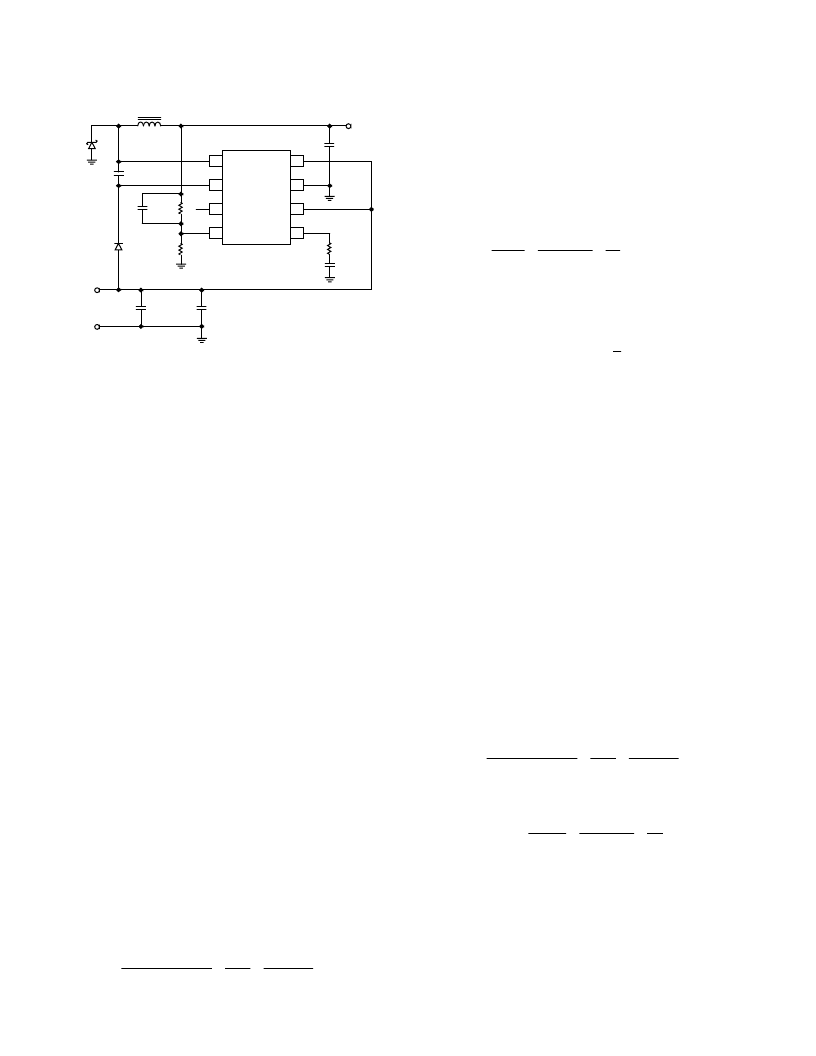
U1
ADP3050
V
IN
1
2
3
4
SWITCH
BOOST
BIAS
FB
IN
GND
SD
COMP
8
7
6
5
R1
20k
R2
21.5k
C
F
C3
0.22 F
D1
1N5817
GND
5V
C1
2 10 F
CERAMIC
+
C2
0.01 F
L1
22 H
V
OUT
2.5V
R
C
7.5k
C
4.7nF
D2
1N4148
+2 22 F
CERAMIC
Figure 23. Adjustable Output Application Circuit
APPLICATION INFORMATION
The complete process for designing a step-down switching regu-
lator using the ADP3050 is given in the following sections. Each
section includes a list of recommended devices. These lists do
not include every available device, nor every available manufac-
turer. They contain only surface-mount devices, but equivalent
through-hole devices can be substituted if needed. In choosing
components, keep in mind what is most important to the design
(efficiency, cost, size, etc.) as these things will ultimately deter-
mine which components are used. Also, make sure the design
specifications are clearly defined and that they reflect the worst-
case conditions. Key specifications include the minimum and
maximum input voltage, the output voltage and ripple, and the
minimum and maximum load current.
INDUCTOR SELECTION
The inductor value will determine the mode of operation for the
regulator: continuous mode, where the inductor current flows
continuously; or discontinuous mode, where the inductor current
reduces to zero during every switch cycle. Continuous mode is
the best choice for many applications. It provides higher output
power, lower peak currents in the switch, inductor, and diode,
and a lower inductor ripple current (which means lower output
ripple voltage). Discontinuous mode does allow the use of smaller
magnetics, but at a price: lower available load current, and higher
peak and ripple currents. Designs with a high input voltage or a
low load current often operate in discontinuous mode to mini-
mize inductor value and size. The ADP3050 is designed to work
well in both modes of operation.
Continuous Mode
The inductor current in a continuous mode system is a triangular
waveform (equal to the ripple current) centered around a dc value
(equal to the load current). The amount of ripple current is deter-
mined by the inductor value, and is usually between 20% and 40%
of the maximum load current. To reduce the inductor size, ripple
currents between 40% and 80% are often used in continuous
mode designs with a high input voltage or a low output current.
The inductor value can be calculated using the following equation:
L
V
V
I
f
V
V
IN
OUT
RIPPLE
SW
OUT
IN
=
×
×
(MAX)
(MAX)
1
(2)
Where
V
IN(MAX)
is the maximum input voltage,
V
OUT
is the regu-
lated output voltage, and
f
SW
is the switching frequency (200 kHz).
The initial choice for the amount of ripple current may seem arbi-
trary, but it will serve as a good starting point for finding a standard
off-the-shelf inductor value (i.e., 10
μ
H, 15
μ
H, 22
μ
H, 33
μ
H, and
47
μ
H). If a specific inductance value is to be used, simply rearrange
the above equation to find the ripple current. For an 800 mA, 12 V
to 5 V system, and a ripple current of 320 mA (40% of 800 mA) is
chosen, the inductance would be:
×
×
0 32
200
10
.
A 47
μ
H inductor is the closest standard value, which gives a ripple
current of about 310 mA. The peak switch current is equal to the
load current plus one-half the ripple current (this is also the peak
current for the inductor and the catch diode):
L
H
=
×
=
μ
12
5
1
5
12
45.
3
I
I
1
2I
0.95 A
=
0.8
0.155
SW(PK)
OUT(MAX)
RIPPLE
=
+
=
+
(3)
Pick an inductor with a dc (or saturation) current rating about
20% larger than
I
SW(PK)
to ensure that the inductor is not running
near the edge of saturation. For this example, 1.20 0.95 A =
1.14 A, so use an inductor with a dc current rating of at least 1.2 A.
The maximum switch current is internally limited to 1.5 A, and
this limit, along with the ripple current, will determine the maxi-
mum load current the system can provide.
If the load current decreases to below one-half the ripple current,
the regulator will operate in discontinuous mode.
Discontinuous Mode
For load currents less than around 0.5 A, discontinuous mode
operation can be used. This will allow the use of a smaller induc-
tor, but the ripple current will be much higher (which means a
higher output ripple voltage). If a larger output capacitor must be
used to reduce the output ripple voltage, the overall system may
actually take up more board area than if a larger inductor was
used. The operation and equations for the two modes are quite
different, but the boundary between these two modes occurs
when the ripple current is equal to twice the load current (when
I
RIPPLE
= 2 I
OUT
). From this we can use Equation 2 to find the
minimum inductor value needed to keep the system in continu-
ous mode operation (solve for the inductor value with I
RIPPLE
=
2 I
OUT
).
×
2
Using an inductor below this value will cause the system to operate
in discontinuous mode. For a 400 mA, 24 V to 5 V system:
L
V
V
I
f
V
V
DIS
IN
OUT
OUT
SW
OUT
IN
=
×
×
(MAX)
(MAX)
1
(4)
L
H
DIS
≤
0 4
.
.
×
24 7
×
×
×
≤
μ
24
2
5
1
200
10
5
24
3
If the chosen inductor value is too small, the internal current
limit will trip each cycle and the regulator will have trouble
providing the necessary load current.
Inductor Core Types and Materials
Many types of inductors are currently available. Numerous core
styles along with numerous core materials often make the selec-
tion process seem even more confusing. A quick overview of the
相關PDF資料 |
PDF描述 |
|---|---|
| ADP3050AR | 200 kHz, 1 A High-Voltage Step-Down Switching Regulator |
| ADP3155 | 5-Bit Programmable Triple Power Supply Controller for Pentium III Processors |
| ADP3155JRU | 5-Bit Programmable Triple Power Supply Controller for Pentium III Processors |
| ADP3156JR-15 | Dual Power Supply Controller for Desktop Systems |
| ADP3156JR-18 | Dual Power Supply Controller for Desktop Systems |
相關代理商/技術參數 |
參數描述 |
|---|---|
| ADP3050AR | 制造商:Analog Devices 功能描述:Conv DC-DC Single Step Down 3.6V to 30V 8-Pin SOIC N 制造商:Rochester Electronics LLC 功能描述:HIGH VOLTAGE STEP DOWN SWITCHING REG. - Bulk 制造商:Analog Devices 功能描述:IC SWITCHING REGULATOR |
| ADP3050AR3.3 | 制造商:Analog Devices 功能描述:IC ((NS)) |
| ADP3050AR-3.3 | 功能描述:IC REG BUCK 3.3V 1A 8SOIC RoHS:否 類別:集成電路 (IC) >> PMIC - 穩壓器 - DC DC 開關穩壓器 系列:- 設計資源:Design Support Tool 標準包裝:1 系列:- 類型:升壓(升壓) 輸出類型:固定 輸出數:1 輸出電壓:3V 輸入電壓:0.75 V ~ 2 V PWM 型:- 頻率 - 開關:- 電流 - 輸出:100mA 同步整流器:是 工作溫度:-40°C ~ 85°C 安裝類型:表面貼裝 封裝/外殼:SOT-23-5 細型,TSOT-23-5 包裝:剪切帶 (CT) 供應商設備封裝:TSOT-23-5 其它名稱:AS1323-BTTT-30CT |
| ADP3050AR-3.3-REEL | 制造商:Analog Devices 功能描述:Conv DC-DC Single Step Down 3.6V to 30V 8-Pin SOIC N T/R |
| ADP3050AR-3.3-RL7 | 功能描述:IC REG BUCK 3.3V 1A 8SOIC RoHS:否 類別:集成電路 (IC) >> PMIC - 穩壓器 - DC DC 開關穩壓器 系列:- 標準包裝:2,500 系列:- 類型:升壓(升壓) 輸出類型:可調式 輸出數:1 輸出電壓:1.24 V ~ 30 V 輸入電壓:1.5 V ~ 12 V PWM 型:電流模式,混合 頻率 - 開關:600kHz 電流 - 輸出:500mA 同步整流器:無 工作溫度:-40°C ~ 85°C 安裝類型:表面貼裝 封裝/外殼:8-SOIC(0.154",3.90mm 寬) 包裝:帶卷 (TR) 供應商設備封裝:8-SOIC |
發布緊急采購,3分鐘左右您將得到回復。