- 您現在的位置:買賣IC網 > PDF目錄374038 > ADT7463ARQ (ANALOG DEVICES INC) dB COOL Remote Thermal Controller and Voltage Monitor PDF資料下載
參數資料
| 型號: | ADT7463ARQ |
| 廠商: | ANALOG DEVICES INC |
| 元件分類: | 模擬信號調理 |
| 英文描述: | dB COOL Remote Thermal Controller and Voltage Monitor |
| 中文描述: | SPECIALTY ANALOG CIRCUIT, PDSO24 |
| 封裝: | MO-137AE, QSOP-24 |
| 文件頁數: | 21/53頁 |
| 文件大小: | 719K |
| 代理商: | ADT7463ARQ |
第1頁第2頁第3頁第4頁第5頁第6頁第7頁第8頁第9頁第10頁第11頁第12頁第13頁第14頁第15頁第16頁第17頁第18頁第19頁第20頁當前第21頁第22頁第23頁第24頁第25頁第26頁第27頁第28頁第29頁第30頁第31頁第32頁第33頁第34頁第35頁第36頁第37頁第38頁第39頁第40頁第41頁第42頁第43頁第44頁第45頁第46頁第47頁第48頁第49頁第50頁第51頁第52頁第53頁
REV. 0
ADT7463
–21–
be masked out to prevent
SMBALERT
interrupts. Note that
masking an interrupt source only prevents the
SMBALERT
output from being asserted; the appropriate Status bit will get
set as normal.
Interrupt Mask Register 1 (Reg. 0x74)
Bit 7 (OOL) = 1,
masks
SMBALERT
for any alert condition
flagged in Status Register 2.
Bit 6 (R2T) = 1,
masks
SMBALERT
for Remote 2 Temperature.
Bit 5 (LT) = 1,
masks
SMBALERT
for Local Temperature.
Bit 4 (R1T) = 1,
masks
SMBALERT
for Remote 1 Temperature.
Bit 3 (5 V) = 1,
masks
SMBALERT
for 5 V channel.
Bit 2 (V
CC
) = 1,
masks
SMBALERT
for V
CC
channel.
Bit 1 (V
CCP
) = 1,
masks
SMBALERT
for V
CCP
channel.
Bit 0 (2.5 V) = 1,
masks
SMBALERT
for 2.5 V channel.
Interrupt Mask Register 2 (Reg. 0x75)
Bit 7 (D2) = 1,
masks
SMBALERT
for Diode 2 errors.
Bit 6 (D1) = 1,
masks
SMBALERT
for Diode 1 errors.
Bit 5 (FAN4) = 1,
masks
SMBALERT
for Fan 4 failure. If the
TACH4 pin is being used as the
THERM
input, this bit masks
SMBALERT
for a
THERM
event.
Bit 4 (FAN3) = 1,
masks
SMBALERT
for Fan 3.
Bit 3 (FAN2) = 1,
masks
SMBALERT
for Fan 2.
Bit 2 (FAN1) = 1,
masks
SMBALERT
for Fan 1.
Bit 1 (OVT) = 1,
masks
SMBALERT
for overtemperature
(exceeding
THERM
limits).
Bit 0 (12V/VC) = 1,
masks
SMBALERT
for 12 V channel or
for a VID Code change, depending on the function used.
Enabling the
SMBALERT
Interrupt Output
The
SMBALERT
interrupt function is disabled by default. Pin
10 or Pin 22 can be reconfigured as an
SMBALERT
output to
signal out-of-limit conditions.
CONFIGURING PIN 10 AS
SMBALERT
OUTPUT
REGISTER
Config Reg 3 (Reg. 0x78)
BIT SETTING
<0> ALERT = 1
CONFIGURING PIN 22 AS
SMBALERT
OUTPUT
REGISTER
Config Reg 4 (Reg. 0x7D)
Therm Input
The ADT7463 has an internal timer to measure
THERM
asser-
tion time. For example, the
THERM
input may be connected
to
the
PROCHOT
output of a Pentium 4 CPU and measure
system performance.
The
THERM
input may also be con-
nected to the output of a trip point temperature sensor.
The timer is started on the assertion of the ADT7463’s
THERM
input, and stopped on the negation of the pin. The
timer counts
THERM
times cumulatively, i.e. the timer
resumes counting on the next
THERM
assertion. The
THERM
timer will continue to accumulate
THERM
assertion times until
the timer is read (it is cleared on read) or until it reaches full
BIT SETTING
<0> AL2.5V = 1
scale. If the counter reaches full scale, it will stop at that reading
until cleared.
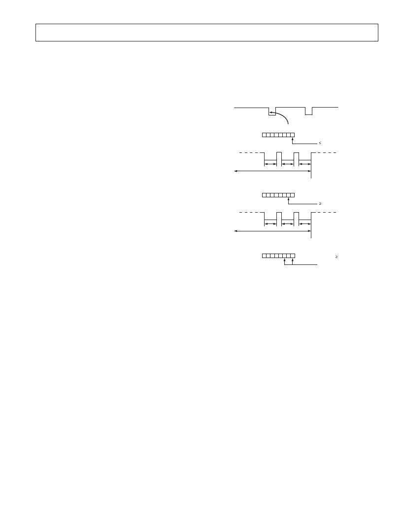
The 8-bit
THERM
Timer register (Reg. 0x79) is designed such
that Bit 0 will get set to 1 on the first
THERM
assertion. Once
the cumulative
THERM
assertion time has exceeded 45.52 ms,
Bit 1 of the
THERM
timer gets set, and Bit 0 now becomes the
LSB of the timer with a resolution of 22.76 ms.
THERM
TIMER
(REG. 0x79)
THERM
0 0 0 0 0 0 1 0
7 6 5 4 3 2 1 0
THERM
ASSERTED
22.76ms
THERM
ACCUMULATE
THERM
LOW
ASSERTION TIMES
THERM
ASSERTED
45.52ms
0 0 0 0 0 1 0 1
7 6 5 4 3 2 1 0
THERM
ASSERTED
113.8ms
(91.04ms + 22.76ms)
THERM
TIMER
(REG. 0x79)
THERM
TIMER
(REG. 0x79)
THERM
ACCUMULATE
THERM
LOW
ASSERTION TIMES
0 0 0 0 0 0 0 1
7 6 5 4 3 2 1 0
Figure 25. Understanding the
THERM
Timer
Figure 25 illustrates how the
THERM
timer behaves as the
THERM
input is asserted and negated. Bit 0 gets set on the
first
THERM
assertion detected. This bit remains set until
such time as the cumulative
THERM
assertions exceed
45.52 ms. At this time, Bit 1 of the
THERM
timer gets set,
and Bit 0 is cleared. Bit 0 now reflects timer readings with a
resolution of 22.76 ms.
When using the
THERM
timer, be aware of the following:
After a
THERM
timer read (Reg. 0x79):
a) The contents of the timer get cleared on read.
b) The F4P bit (Bit 5) of Status Register 2 needs to be cleared
(assuming the
THERM
limit has been exceeded).
If the
THERM
timer is read during a
THERM
assertion, then
the following will happen:
a) The contents of the timer are cleared.
b) Bit 0 of the
THERM
timer is set to 1 (since a
THERM
assertion is occurring).
c) The
THERM
timer increments from zero.
d) If the
THERM
limit (Reg. 0x7A) = 0x00, then the F4P bit
gets set.
Generating
SMBALERT
Interrupts from
THERM
Events
The ADT7463 can generate
SMBALERT
s when a program-
mable
THERM
limit has been exceeded. This allows the
systems designer to ignore brief, infrequent
THERM
assertions,
while capturing longer
THERM
events. Register 0x7A is the
THERM
Limit Register. This 8-bit register allows a limit from
相關PDF資料 |
PDF描述 |
|---|---|
| ADT7466 | dBCool Remote Thermal Controller and Voltage Monitor |
| ADT7466ARQZ | dBCool Remote Thermal Controller and Voltage Monitor |
| ADT7466ARQZ-REEL | dBCool Remote Thermal Controller and Voltage Monitor |
| ADT7466ARQZ-REEL7 | dBCool Remote Thermal Controller and Voltage Monitor |
| ADT7516 | SPI/I2C Compatible, Temperature Sensor, Four Channel ADC and Quad Voltage Output DAC |
相關代理商/技術參數 |
參數描述 |
|---|---|
| ADT7463ARQ-REEL | 功能描述:IC SENSOR TEMP FAN-CTRL 24QSOP RoHS:否 類別:集成電路 (IC) >> PMIC - 熱管理 系列:dBCool® 標準包裝:1 系列:- 功能:溫度監控系統(傳感器) 傳感器類型:內部和外部 感應溫度:-40°C ~ 125°C,外部傳感器 精確度:±2.5°C 本地(最大值),±5°C 遠程(最大值) 拓撲:ADC,比較器,寄存器庫 輸出類型:2 線 SMBus? 輸出警報:無 輸出風扇:無 電源電壓:2.7 V ~ 5.5 V 工作溫度:-40°C ~ 125°C 安裝類型:表面貼裝 封裝/外殼:SOT-23-8 供應商設備封裝:SOT-23-8 包裝:Digi-Reel® 其它名稱:296-22675-6 |
| ADT7463ARQ-REEL7 | 功能描述:IC SENSOR TEMP FAN-CTRL 24QSOP RoHS:否 類別:集成電路 (IC) >> PMIC - 熱管理 系列:dBCool® 標準包裝:1 系列:- 功能:溫度監控系統(傳感器) 傳感器類型:內部和外部 感應溫度:-40°C ~ 125°C,外部傳感器 精確度:±2.5°C 本地(最大值),±5°C 遠程(最大值) 拓撲:ADC,比較器,寄存器庫 輸出類型:2 線 SMBus? 輸出警報:無 輸出風扇:無 電源電壓:2.7 V ~ 5.5 V 工作溫度:-40°C ~ 125°C 安裝類型:表面貼裝 封裝/外殼:SOT-23-8 供應商設備封裝:SOT-23-8 包裝:Digi-Reel® 其它名稱:296-22675-6 |
| ADT7463ARQZ | 功能描述:馬達/運動/點火控制器和驅動器 SYS MGMT CNTRLR IC RoHS:否 制造商:STMicroelectronics 產品:Stepper Motor Controllers / Drivers 類型:2 Phase Stepper Motor Driver 工作電源電壓:8 V to 45 V 電源電流:0.5 mA 工作溫度:- 25 C to + 125 C 安裝風格:SMD/SMT 封裝 / 箱體:HTSSOP-28 封裝:Tube |
| ADT7463ARQZ-R7 | 功能描述:板上安裝溫度傳感器 SYS MGMT CNTRLR IC RoHS:否 制造商:Omron Electronics 輸出類型:Digital 配置: 準確性:+/- 1.5 C, +/- 3 C 溫度閾值: 數字輸出 - 總線接口:2-Wire, I2C, SMBus 電源電壓-最大:5.5 V 電源電壓-最小:4.5 V 最大工作溫度:+ 50 C 最小工作溫度:0 C 關閉: 安裝風格: 封裝 / 箱體: 設備功能:Temperature and Humidity Sensor |
| ADT7463ARQZ-REEL | 功能描述:板上安裝溫度傳感器 SYS MGMT CNTRLR IC RoHS:否 制造商:Omron Electronics 輸出類型:Digital 配置: 準確性:+/- 1.5 C, +/- 3 C 溫度閾值: 數字輸出 - 總線接口:2-Wire, I2C, SMBus 電源電壓-最大:5.5 V 電源電壓-最小:4.5 V 最大工作溫度:+ 50 C 最小工作溫度:0 C 關閉: 安裝風格: 封裝 / 箱體: 設備功能:Temperature and Humidity Sensor |
發布緊急采購,3分鐘左右您將得到回復。