- 您現在的位置:買賣IC網 > PDF目錄374038 > ADUC7022ACP32 (ANALOG DEVICES INC) Precision Analog Microcontroller 12-bit Analog I/O, ARM7TDMI MCU PDF資料下載
參數資料
| 型號: | ADUC7022ACP32 |
| 廠商: | ANALOG DEVICES INC |
| 元件分類: | 微控制器/微處理器 |
| 英文描述: | Precision Analog Microcontroller 12-bit Analog I/O, ARM7TDMI MCU |
| 中文描述: | 32-BIT, FLASH, 45.5 MHz, MICROCONTROLLER, QCC40 |
| 封裝: | 6 X 6 MM, MO-220VJJD-2, LFCSP-40 |
| 文件頁數: | 36/80頁 |
| 文件大小: | 840K |
| 代理商: | ADUC7022ACP32 |
第1頁第2頁第3頁第4頁第5頁第6頁第7頁第8頁第9頁第10頁第11頁第12頁第13頁第14頁第15頁第16頁第17頁第18頁第19頁第20頁第21頁第22頁第23頁第24頁第25頁第26頁第27頁第28頁第29頁第30頁第31頁第32頁第33頁第34頁第35頁當前第36頁第37頁第38頁第39頁第40頁第41頁第42頁第43頁第44頁第45頁第46頁第47頁第48頁第49頁第50頁第51頁第52頁第53頁第54頁第55頁第56頁第57頁第58頁第59頁第60頁第61頁第62頁第63頁第64頁第65頁第66頁第67頁第68頁第69頁第70頁第71頁第72頁第73頁第74頁第75頁第76頁第77頁第78頁第79頁第80頁
ADuC702x Series
Preliminary Technical Data
RESET AND REMAP
Rev. PrB | Page 36 of 80
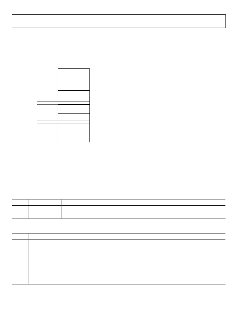
The ARM exception vectors are all situated at the bottom of the
memory array, from address 0x00000000 to address 0x00000020
as shown Figure 16.
00000000h
Mirror Space
0008FFFFh
00080000h
Flash/EE
00011FFFh
00010000h
SRAM
FFFFFFFFh
0x00000000
0x00000020
kernel
interrupt
service routines
interrupt
service routines
ARM exception
vector addresses
Figure 16: remap for exception execution
By default and after any reset, the Flash/EE is mirrored at the
bottom of the memory array. The remap function allows the
programmer to mirror the SRAM at the bottom of the memory
array, facilitating execution of exception routines from SRAM
instead of from Flash/EE. This means exceptions are executed
twice as fast, exception being executed in ARM mode (32 bit)
and the SRAM being 32-bit wide instead of 16-bit wide
Flash/EE memory.
Remap operation
When a reset occurs on the ADuC702x, execution starts
automatically in factory programmed internal configuration
code. This so called kernel is hidden and cannot be accessed by
user code. If the ADuC702x is in normal mode (BM pin is
high), it will execute the power-on configuration routine of the
kernel and then jump to the reset vector address, 0x00000000, to
execute the users reset exception routine.
Because the Flash/EE is mirrored at the bottom of the memory
array at reset, the reset interrupt routine must always be written
in Flash/EE.
The remap is done from Flash/EE by setting bit0 of the REMAP
register. Precaution must be taken to execute this command
from Flash/EE, above address 0x00080020, and not from the
bottom of the array as this will be replaced by the SRAM.
This operation is reversible: the Flash/EE can be remapped at
address 0x00000000 by clearing Bit0 of the REMAP MMR.
Precaution must again be taken to execute the remap function
from outside the mirrored area. Any kind of reset will remap the
Flash /EE memory at the bottom of the array.
Reset
There are four kinds of reset: external reset, Power-on-reset,
watchdog expiation and software force. The RSTSTA register
indicates the source of the last reset and RSTCLR allows to clear
the RSTSTA register. These registers can be used during a reset
exception service routine to identify the source of the reset. If
RSTSTA is null, the reset was external.
Table 17: REMAP MMR bit designations
Bit
0
Name
Remap
Description
Remap Bit.
Set
by the user to remap the SRAM to address 0x00000000.
Cleared
automatically after reset to remap the Flash/EE memory to address 0x00000000.
Table 18: RSTSTA MMR bit designations
Bit
7-3
2
Description
Reserved
Software reset
Set
by user to force a software reset.
Cleared
by setting the corresponding bit in RSTCLR
Watchdog timeout
Set
automatically when a watchdog timeout occurs
Cleared
by setting the corresponding bit in RSTCLR
Power-on-reset
Set
automatically when a power-on-reset occurs
Cleared
by setting the corresponding bit in RSTCLR
1
0
相關PDF資料 |
PDF描述 |
|---|---|
| ADUC7022BCP32 | Precision Analog Microcontroller 12-bit Analog I/O, ARM7TDMI MCU |
| ADUC7022BCP62 | Precision Analog Microcontroller 12-bit Analog I/O, ARM7TDMI MCU |
| ADUC7024BCP62 | Precision Analog Microcontroller 12-bit Analog I/O, ARM7TDMI MCU |
| ADUC7024BST62 | Precision Analog Microcontroller 12-bit Analog I/O, ARM7TDMI MCU |
| ADUC7025BCP32 | Precision Analog Microcontroller 12-bit Analog I/O, ARM7TDMI MCU |
相關代理商/技術參數 |
參數描述 |
|---|---|
| ADUC7022ACPZ32 | 制造商:Analog Devices 功能描述:MCU 32BIT RISC 32KB FLASH 3.3V 40LFCSP EP - Trays |
| ADUC7022BCP32 | 制造商:Analog Devices 功能描述:FLASH ARM7+10-CH,12-B ADC IC - Trays |
| ADUC7022BCP62 | 制造商:Analog Devices 功能描述:FLASH ARM7+10-CH,12-B ADC IC - Trays |
| ADUC7022BCP62-U1 | 制造商:Analog Devices 功能描述: |
| ADUC7022BCPZ32 | 功能描述:IC MCU FLSH 32K ANLG I/O 40LFCSP RoHS:是 類別:集成電路 (IC) >> 嵌入式 - 微控制器, 系列:MicroConverter® ADuC7xxx 標準包裝:250 系列:LPC11Uxx 核心處理器:ARM? Cortex?-M0 芯體尺寸:32-位 速度:50MHz 連通性:I²C,Microwire,SPI,SSI,SSP,UART/USART,USB 外圍設備:欠壓檢測/復位,POR,WDT 輸入/輸出數:40 程序存儲器容量:96KB(96K x 8) 程序存儲器類型:閃存 EEPROM 大小:4K x 8 RAM 容量:10K x 8 電壓 - 電源 (Vcc/Vdd):1.8 V ~ 3.6 V 數據轉換器:A/D 8x10b 振蕩器型:內部 工作溫度:-40°C ~ 85°C 封裝/外殼:48-LQFP 包裝:托盤 其它名稱:568-9587 |
發布緊急采購,3分鐘左右您將得到回復。