- 您現在的位置:買賣IC網 > PDF目錄374038 > ADUC7022ACP32 (ANALOG DEVICES INC) Precision Analog Microcontroller 12-bit Analog I/O, ARM7TDMI MCU PDF資料下載
參數資料
| 型號: | ADUC7022ACP32 |
| 廠商: | ANALOG DEVICES INC |
| 元件分類: | 微控制器/微處理器 |
| 英文描述: | Precision Analog Microcontroller 12-bit Analog I/O, ARM7TDMI MCU |
| 中文描述: | 32-BIT, FLASH, 45.5 MHz, MICROCONTROLLER, QCC40 |
| 封裝: | 6 X 6 MM, MO-220VJJD-2, LFCSP-40 |
| 文件頁數: | 52/80頁 |
| 文件大小: | 840K |
| 代理商: | ADUC7022ACP32 |
第1頁第2頁第3頁第4頁第5頁第6頁第7頁第8頁第9頁第10頁第11頁第12頁第13頁第14頁第15頁第16頁第17頁第18頁第19頁第20頁第21頁第22頁第23頁第24頁第25頁第26頁第27頁第28頁第29頁第30頁第31頁第32頁第33頁第34頁第35頁第36頁第37頁第38頁第39頁第40頁第41頁第42頁第43頁第44頁第45頁第46頁第47頁第48頁第49頁第50頁第51頁當前第52頁第53頁第54頁第55頁第56頁第57頁第58頁第59頁第60頁第61頁第62頁第63頁第64頁第65頁第66頁第67頁第68頁第69頁第70頁第71頁第72頁第73頁第74頁第75頁第76頁第77頁第78頁第79頁第80頁
ADuC702x Series
Preliminary Technical Data
SERIAL PORT MUX
Rev. PrB | Page 52 of 80
The Serial Port Mux multiplexes the serial port peripherals (two
I
2
C, SPI, UART) and the Programmable Logic Array (PLA) to a
set of ten GPIO pins. Each pin must be configured to one of its
specific I/O function as described in Table 34.
GPIO
00
P1.0
P1.1
P1.2
P1.3
P1.4
P1.5
P1.6
P1.7
P0.7
P2.0
UART
01
SIN
SOUT
RTS
CTS
RI
DCD
DSR
DTR
ECLK
CONV
Table 34: SPM configuration
UART/I
2
C/SPI
10
I2C0SCL
I2C0SDA
I2C1SCL
I2C1SDA
SPICLK
SPIMISO
SPIMOSI
SPICSL
SIN
SOUT
PLA
11
PLAI[0]
PLAI[1]
PLAI[2]
PLAI[3]
PLAI[4]
PLAI[5]
PLAI[6]
PLAO[0]
PLAO[4]
PLAO[5]
SPM0
SPM1
SPM2
SPM3
SPM4
SPM5
SPM6
SPM7
SPM8
SPM9
Table 34 details the mode for each of the SPMUX GPIO pins.
This configuration has to be done via
the GP0CON, GP1CON
and GP2CON MMRs. By default these ten pins are configured
as GPIOs.
UART SERIAL INTERFACE
The UART peripheral is a full-duplex Universal Asynchronous
Receiver/Transmitter, fully compatible with the 16450 serial
port standard. The UART performs serial-to-parallel conversion
on data characters received from a peripheral device or a
MODEM, and parallel-to-serial conversion on data characters
received from the CPU. The UART includes a fractional divider
for baudrate generation and has a network addressable mode.
The UART function is made available on the following 10 pins
of the ADuC702x:
Pin
SPM0 (mode 1)
SPM1 (mode 1)
SPM2 (mode 1)
SPM3 (mode 1)
SPM4 (mode 1)
SPM5 (mode 1)
SPM6 (mode 1)
SPM7 (mode 1)
SPM8 (mode 2)
SPM9 (mode 2)
Signal
RTS
CTS
SIN
SOUT
RI
DCD
DSR
DTR
SIN
SOUT
Table 35: UART signal description
Description
Request To Send
Clear To Send
Serial Receive Data
Serial Transmit Data
Ring Indicator
Data Carrier Detect
Data Set Ready
Data Terminal Ready
Serial Receive Data
Serial Transmit Data
The serial communication adopts a asynchronous protocol that
supports various word length, stop bits and parity generation
options selectable in the configuration register.
Baud rate generation
There is two way of generating the UART baudrate.
-
Normal 450 UART baudrate generation:
The baudrate is a divided version of the core clock using the
value in COMDIV0 and COMDIV1 MMRs (16-bit value, DL).
DL
MHz
×
×
2
Baudrate
CD
×
=
16
2
088
.
45
The following table gives some common baudrate values:
Baudrate
CD
DL
Actual
baudrate
% error
9600
19200
115200
9600
19200
115200
0
0
0
3
3
3
92h
49h
0Ch
12h
9h
1h
9651
19301
117417
9785
19569
88062
0.53%
0.53%
1.92%
1.92%
1.92%
23.55%
Table 36: baudrate using the normal baudrate generator
-
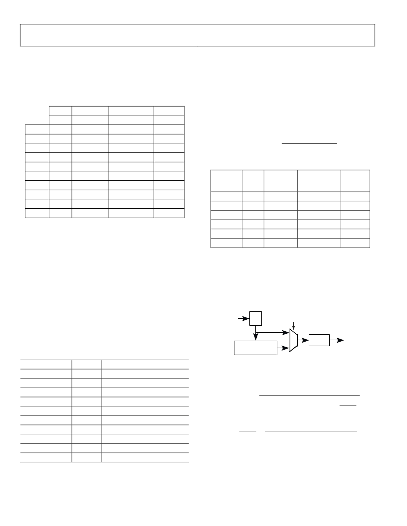
Using the fractional divider:
The fractional divider combined with the normal baudrate
generator allows the generating of a wider range of more
accurate baudrates.
Core Clock
/(M+N/2048)
/16DL
UART
FBEN
/2
Figure 26: baudrate generation options
Calculation of the baudrate using fractional divider is as follow:
)
2048
(
2
16
2
088
.
45
N
M
DL
MHz
Baudrate
CD
+
×
×
×
×
=
2
16
2
088
.
×
45
2048
×
×
×
=
+
DL
Baudrate
MHz
N
M
CD
Example:
Generation of 9600 baud with CD bits = 3. The previous table
gives DL = 12h.
相關PDF資料 |
PDF描述 |
|---|---|
| ADUC7022BCP32 | Precision Analog Microcontroller 12-bit Analog I/O, ARM7TDMI MCU |
| ADUC7022BCP62 | Precision Analog Microcontroller 12-bit Analog I/O, ARM7TDMI MCU |
| ADUC7024BCP62 | Precision Analog Microcontroller 12-bit Analog I/O, ARM7TDMI MCU |
| ADUC7024BST62 | Precision Analog Microcontroller 12-bit Analog I/O, ARM7TDMI MCU |
| ADUC7025BCP32 | Precision Analog Microcontroller 12-bit Analog I/O, ARM7TDMI MCU |
相關代理商/技術參數 |
參數描述 |
|---|---|
| ADUC7022ACPZ32 | 制造商:Analog Devices 功能描述:MCU 32BIT RISC 32KB FLASH 3.3V 40LFCSP EP - Trays |
| ADUC7022BCP32 | 制造商:Analog Devices 功能描述:FLASH ARM7+10-CH,12-B ADC IC - Trays |
| ADUC7022BCP62 | 制造商:Analog Devices 功能描述:FLASH ARM7+10-CH,12-B ADC IC - Trays |
| ADUC7022BCP62-U1 | 制造商:Analog Devices 功能描述: |
| ADUC7022BCPZ32 | 功能描述:IC MCU FLSH 32K ANLG I/O 40LFCSP RoHS:是 類別:集成電路 (IC) >> 嵌入式 - 微控制器, 系列:MicroConverter® ADuC7xxx 標準包裝:250 系列:LPC11Uxx 核心處理器:ARM? Cortex?-M0 芯體尺寸:32-位 速度:50MHz 連通性:I²C,Microwire,SPI,SSI,SSP,UART/USART,USB 外圍設備:欠壓檢測/復位,POR,WDT 輸入/輸出數:40 程序存儲器容量:96KB(96K x 8) 程序存儲器類型:閃存 EEPROM 大小:4K x 8 RAM 容量:10K x 8 電壓 - 電源 (Vcc/Vdd):1.8 V ~ 3.6 V 數據轉換器:A/D 8x10b 振蕩器型:內部 工作溫度:-40°C ~ 85°C 封裝/外殼:48-LQFP 包裝:托盤 其它名稱:568-9587 |
發布緊急采購,3分鐘左右您將得到回復。