- 您現在的位置:買賣IC網 > PDF目錄374047 > ADV7190KST (ANALOG DEVICES INC) Video Encoder with Six 10-Bit DACs and Video Encoder with Six DAC Outputs PDF資料下載
參數資料
| 型號: | ADV7190KST |
| 廠商: | ANALOG DEVICES INC |
| 元件分類: | 顏色信號轉換 |
| 英文描述: | Video Encoder with Six 10-Bit DACs and Video Encoder with Six DAC Outputs |
| 中文描述: | COLOR SIGNAL ENCODER, PQFP64 |
| 封裝: | LQFP-64 |
| 文件頁數: | 31/69頁 |
| 文件大小: | 628K |
| 代理商: | ADV7190KST |
第1頁第2頁第3頁第4頁第5頁第6頁第7頁第8頁第9頁第10頁第11頁第12頁第13頁第14頁第15頁第16頁第17頁第18頁第19頁第20頁第21頁第22頁第23頁第24頁第25頁第26頁第27頁第28頁第29頁第30頁當前第31頁第32頁第33頁第34頁第35頁第36頁第37頁第38頁第39頁第40頁第41頁第42頁第43頁第44頁第45頁第46頁第47頁第48頁第49頁第50頁第51頁第52頁第53頁第54頁第55頁第56頁第57頁第58頁第59頁第60頁第61頁第62頁第63頁第64頁第65頁第66頁第67頁第68頁第69頁
ADV7190/ADV7191
–31–
REV. 0
MODE REGISTER 3
MR3 (MR37–MR30)
(Address (SR4–SR0) = 03H)
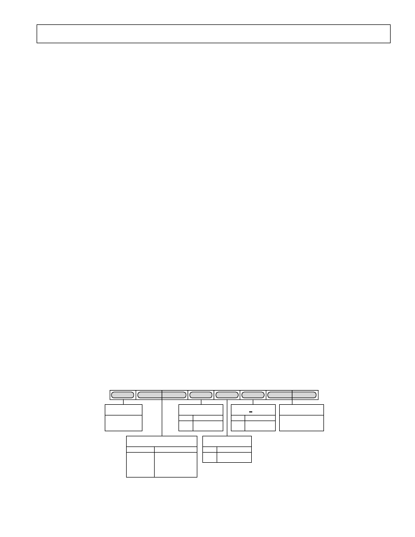
Mode Register 3 is a 8-bit wide register. Figure 53 shows the
various operations under the control of Mode Register 3.
MR3 BIT DESCRIPTION
Revision Code (MR30–MR31)
This bit is read only and indicates the revision of the device.
VBI_Open (MR32)
This bit determines whether or not data in the Vertical Blanking
Interval (VBI) is output to the analog outputs or blanked. Note
that this condition is also valid in Timing Slave Mode 0. For
further information see Vertical Blanking Data Insertion and
BLANK
Input section.
Teletext Enable (MR33)
This bit must be set to 1 to enable teletext data insertion on
the TTX pin.
Teletext Bit Request Mode Control (MR34)
This bit enables switching of the teletext request signal from a
continuous high signal (MR34 = 0) to a bitwise request signal
(MR34 = 1).
Closed Captioning Field Control (MR35–MR36)
These bits control the fields that closed captioning data is dis-
played on, closed captioning information can be displayed on
an odd field, even field or both fields.
Reserved (MR37)
A Logic 0 must be written to this bit.
MODE REGISTER 4
MR4 (MR47–MR40)
(Address (SR4–SR0) = 04H)
Mode Register 4 is a 8-bit wide register. Figure 54 shows the
various operations under the control of Mode Register 4.
MR4 BIT DESCRIPTION
VSYNC_3H Control (MR40)
When this bit is enabled (1) in Slave Mode, it is possible to
drive the
VSYNC
input low for 2.5 lines in PAL mode and
three lines in NTSC mode. When this bit is enabled in Master
Mode the ADV7190/ADV7191 outputs an active low
VSYNC
signal for three lines in NTSC mode and 2.5 lines in PAL mode.
Genlock Control (MR41–MR42)
These bits control the Genlock feature and timing reset of
the ADV7190/ADV7191 Setting MR41 and MR42 to Logic 0
disables the SCRESET/RTC/TR pin and allows the ADV7190/
ADV7191 to operate in normal mode.
1. By setting MR41 to zero and MR42 to one a timing reset is
applied, resetting the horizontal and vertical counters. This
has the effect of resetting the Field Count to Field 0.
If the SCRESET/RTC/TR pin is held high, the counters
will remain reset. Once the pin is released the counters will
commence counting again. For correct counter reset, the
SCRESET/RTC/TR pin has to remain high for at least
37 ns (one clock cycle at 27 MHz).
2. If MR41 is set to one and MR42 is set to zero, the SCRESET/
RTC/TR pin is configured as a subcarrier reset input and
the subcarrier phase will reset to Field 0 whenever a low-to-
high transition is detected on the SCRESET/RTC/TR pin
(SCH phase resets at the start of the next field).
3. If MR41 is set to one and MR42 is set to one, the SCRESET/
RTC/TR pin is configured as a real-time control input and
the ADV7190/ADV7191 can be used to lock to an external
video source working in RTC mode. For more information see
Real-Time Control, Subcarrier Reset and Timing Reset section.
Active Video Line Duration (MR43)
This bit switches between two active video line durations. A zero
selects CCIR Rec. 601 (720 pixels PAL/NTSC) and a one
selects ITU-R BT. 470 standard for active video duration (710
pixels NTSC, 702 pixels PAL).
Chrominance Control (MR44)
This bit enables the color information to be switched on and off
the chroma composite, color component outputs.
Burst Control (MR45)
This bit enables the color burst to be switched on and off the
chroma and composite outputs.
Color Bar Control (MR46)
This bit can be used to generate and output an internal color
bar test pattern. The color bar configuration is 100/7.5/75/7.5
for NTSC and 100/0/75/0 for PAL. It is important to note that
when color bars are enabled the ADV7190/ADV7191 is con-
figured in a Master Timing mode. The output pins
VSYNC
,
HSYNC
and
BLANK
are three-state during color bar mode.
MR37
ZERO MUST BE
WRITTEN TO
THIS BIT
MR37
MR36
MR35
MR34
MR33
MR32
MR31
MR30
MR31 MR30
RESERVED FOR
REVISION CODE
VBI OPEN
0
1
DISABLE
ENABLE
MR32
TTX BIT REQUEST
MODE CONTROL
MR34
0
1
DISABLE
ENABLE
TELETEXT
ENABLE
0
1
DISABLE
ENABLE
MR33
CLOSED CAPTIONING
FIELD CONTROL
MR36 MR35
0 0 NO DATA OUT
0
1
1
0
1
1
ODD FIELD ONLY
EVEN FIELD ONLY
DATA OUT
(BOTH FIELDS)
Figure 53. Mode Register 3 (MR3)
相關PDF資料 |
PDF描述 |
|---|---|
| ADV7191 | Video Encoder with Six 10-Bit DACs and Video Encoder with Six DAC Outputs |
| ADV7191KST | Video Encoder with Six 10-Bit DACs and Video Encoder with Six DAC Outputs |
| ADV7190 | Video Encoder with Six 10-Bit DACs and Video Encoder with Six DAC Outputs |
| ADV7192KST | Video Encoder with Six 10-Bit DACs, 54 MHz Oversampling and Progressive Scan Inputs |
| ADV7192 | Video Encoder with Six 10-Bit DACs, 54 MHz Oversampling and Progressive Scan Inputs |
相關代理商/技術參數 |
參數描述 |
|---|---|
| ADV7190KSTZ | 制造商:Analog Devices 功能描述:Video Encoder 6DAC 10-Bit 64-Pin LQFP |
| ADV7191 | 制造商:AD 制造商全稱:Analog Devices 功能描述:Video Encoder with Six 10-Bit DACs and Video Encoder with Six DAC Outputs |
| ADV7191KST | 制造商:Analog Devices 功能描述:Video Encoder 6DAC 10-Bit 64-Pin LQFP 制造商:Rochester Electronics LLC 功能描述:54M 4X STD DEF ENCODER NON-MACRO I.C. - Tape and Reel |
| ADV7191KSTZ | 制造商:Analog Devices 功能描述:Video Encoder 6DAC 10-Bit 64-Pin LQFP 制造商:Analog Devices 功能描述:IC VIDEO ENCODER |
| ADV7192 | 制造商:AD 制造商全稱:Analog Devices 功能描述:Video Encoder with Six 10-Bit DACs, 54 MHz Oversampling and Progressive Scan Inputs |
發布緊急采購,3分鐘左右您將得到回復。