- 您現在的位置:買賣IC網 > PDF目錄36724 > APT60GT60SR (MICROSEMI POWER PRODUCTS GROUP) 100 A, 600 V, N-CHANNEL IGBT PDF資料下載
參數資料
| 型號: | APT60GT60SR |
| 廠商: | MICROSEMI POWER PRODUCTS GROUP |
| 元件分類: | IGBT 晶體管 |
| 英文描述: | 100 A, 600 V, N-CHANNEL IGBT |
| 封裝: | D3PAK-3 |
| 文件頁數: | 1/5頁 |
| 文件大小: | 253K |
| 代理商: | APT60GT60SR |
052-6223
Rev
D
6
-200
8
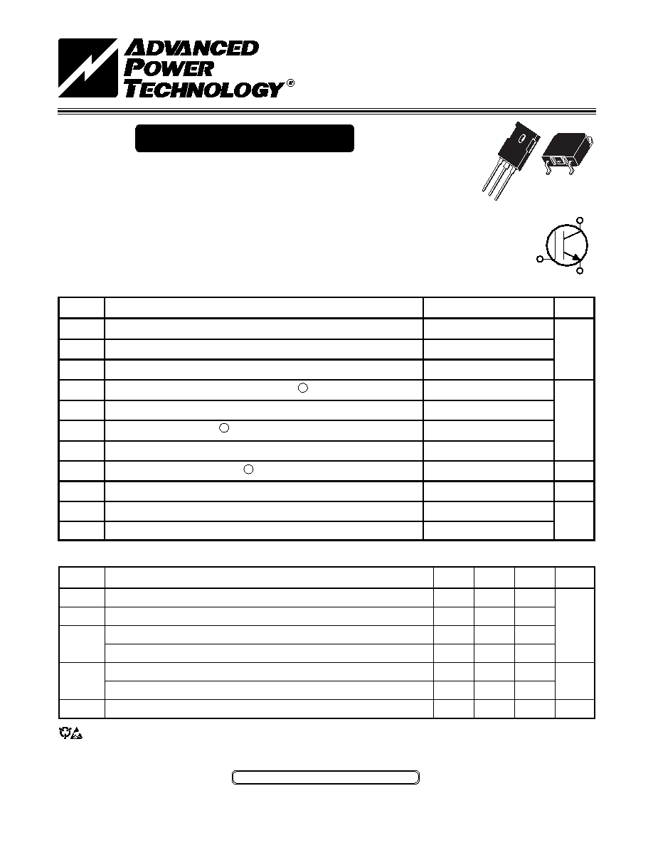
APT60GT60BR_SR
G
C
E
APT60GT60BR
APT60GT60SR
600V
The Thunderbolt IGBT is a new generation of high voltage power IGBTs.
Using Non-Punch Through Technology the Thunderbolt IGBT offers superior
ruggedness and ultrafast switching speed.
Low Forward Voltage Drop
High Freq. Switching to 150KHz
Low Tail Current
Ultra Low Leakage Current
Avalanche Rated
RBSOA and SCSOA Rated
Thunderbolt IGBT
MAXIMUM RATINGS
All Ratings: TC = 25°C unless otherwise specified.
STATIC ELECTRICAL CHARACTERISTICS
CAUTION: These Devices are Sensitive to Electrostatic Discharge. Proper Handling Procedures Should Be Followed.
APT Website - http://www.advancedpower.com
MIN
TYP
MAX
600
345
1.6
2.2
2.5
2.8
80
2000
±100
Characteristic / Test Conditions
Collector-Emitter Breakdown Voltage (VGE = 0V, IC = 0.5mA)
Gate Threshold Voltage (VCE = VGE, IC = 500A, Tj = 25°C)
Collector-Emitter On Voltage (VGE = 15V, IC = IC2, Tj = 25°C)
Collector-Emitter On Voltage (VGE = 15V, IC = IC2, Tj = 125°C)
Collector Cut-off Current (VCE = VCES, VGE = 0V, Tj = 25°C)
Collector Cut-off Current (VCE = VCES, VGE = 0V, Tj = 125°C)
Gate-Emitter Leakage Current (VGE = ±20V, VCE = 0V)
Symbol
BVCES
VGE(TH)
VCE(ON)
ICES
IGES
UNIT
Volts
A
nA
Symbol
VCES
VCGR
VGE
IC1
IC2
ICM
ILM
EAS
PD
TJ,TSTG
TL
Parameter
Collector-Emitter Voltage
Collector-Gate Voltage (RGE = 20K)
Gate Emitter Voltage
Continuous Collector Current @ TC = 25°C 4
Continuous Collector Current @ TC = 105°C
Pulsed Collector Current 1 @ TC = 25°C
RBSOA Clamped Inductive Load Current RG = 11 TC = 25°C
Single Pule Avalanche Energy 2
Total Power Dissipation
Operating and Storage Junction Temperature Range
Max. Lead Temp. for Soldering: 0.063" from Case for 10 Sec.
APT60GT60BR_SR
600
±20
100
60
360
65
500
-55 to 150
300
UNIT
Volts
Amps
mJ
Watts
°C
TO
-24
7
G
C
E
D3PAK
G
C
E
(B)
(S)
相關PDF資料 |
PDF描述 |
|---|---|
| APT60GT60BR | 100 A, 600 V, N-CHANNEL IGBT, TO-247AD |
| APT60GU30B | 100 A, 300 V, N-CHANNEL IGBT, TO-247AD |
| APT60GU30S | 100 A, 300 V, N-CHANNEL IGBT |
| APT60GU30SG | 100 A, 300 V, N-CHANNEL IGBT |
| APT60GU30BG | 100 A, 300 V, N-CHANNEL IGBT, TO-247AD |
相關代理商/技術參數 |
參數描述 |
|---|---|
| APT60GT60SRG | 制造商:Microsemi Corporation 功能描述:POWER IGBT TRANSISTOR |
| APT60GU30B | 制造商:ADPOW 制造商全稱:Advanced Power Technology 功能描述:POWER MOS 7 IGBT |
| APT60GU30S | 制造商:ADPOW 制造商全稱:Advanced Power Technology 功能描述:POWER MOS 7 IGBT |
| APT60M60JFLL | 功能描述:MOSFET N-CH 600V 70A SOT-227 RoHS:是 類別:半導體模塊 >> FET 系列:POWER MOS 7® 標準包裝:10 系列:* |
| APT60M60JFLL_03 | 制造商:ADPOW 制造商全稱:Advanced Power Technology 功能描述:POWER MOS 7 R FREDFET |
發(fā)布緊急采購,3分鐘左右您將得到回復。