- 您現在的位置:買賣IC網 > PDF目錄379702 > AVPRO5002C-CGT (Electronic Theatre Controls, Inc.) Dual SCART A/V Switch PDF資料下載
參數資料
| 型號: | AVPRO5002C-CGT |
| 廠商: | Electronic Theatre Controls, Inc. |
| 英文描述: | Dual SCART A/V Switch |
| 中文描述: | 雙SCART A / V開關 |
| 文件頁數: | 4/23頁 |
| 文件大小: | 106K |
| 代理商: | AVPRO5002C-CGT |
AVPro
5002C
Dual SCART A/V Switch
4
video output load. The
TV_G
and
TV_B
outputs will
be set to 0 VDC when the SVHS mode is active.
RF MODULATOR OUTPUT
The device provides an output,
Mod_YC
, to drive an
external RF modulator. The
Mod_YC
output is a
unity gain amplifier designed to drive a 1k load or
higher. When the device is operating in the RGB
mode, the signal on the
Mod_YC
output will follow
the same source as the RGB and
TV_YCout
outputs.
When the device is in the SVHS mode, the
Mod_YC
output can be driven by several sources depending
on the SVHS video source. These various options
are detailed in the serial port register table.
One case that requires additional detail is the
auxiliary SVHS mode. In the SVHS mode, the
Aux_YC
video input will only provide luma
information. Composite video for the modulator
output must be generated by summing this luma
information with chroma information from the
auxiliary port. The input pin labeled
Aux_Cin
is used
for this purpose. The
Aux_Cin
input pin is AC
coupled to the same source that provides the input
signal to
Aux_R
. An internal summing node
combines the video signal on
Aux_Cin
(chroma) with
the video signal on
Aux_YC
(luma) to generate a
composite video signal. In the auxiliary SVHS mode,
this signal is provided at the
Mod_YC
pin.
TV COMPOSITE VIDEO MUTE
The TV composite video outputs can be muted by
programming the lower three (3) bits in Register 1.
The power-up default condition is xxxxx111, which
sets the TV composite video outputs to 0 VDC and
switches the TV audio outputs to Aux_
Lin/Aux_Rin
.
Setting these bits to xxxxx110 will also mute the TV
composite video outputs and switch the TV audio
outputs to
Lin/Rin
.
AUXILIARY COMPOSITE OUTPUT
The auxiliary port includes a composite video output
pin (
AUX_YCout
) that is typically connected to the
“Video Out” pin on an auxiliary SCART connector.
Bits 3-5 in Register 1 determine the source for the
AUX_YCout
pin. When these bits are set to
xx000xxx, the video source will be the
Enc_B
input.
When these bits are set to xx001xxx, the video
source will be the
Enc_YC
input. When these bits
are set to xx010xxx, the video source will be the
TV_YCin
input.
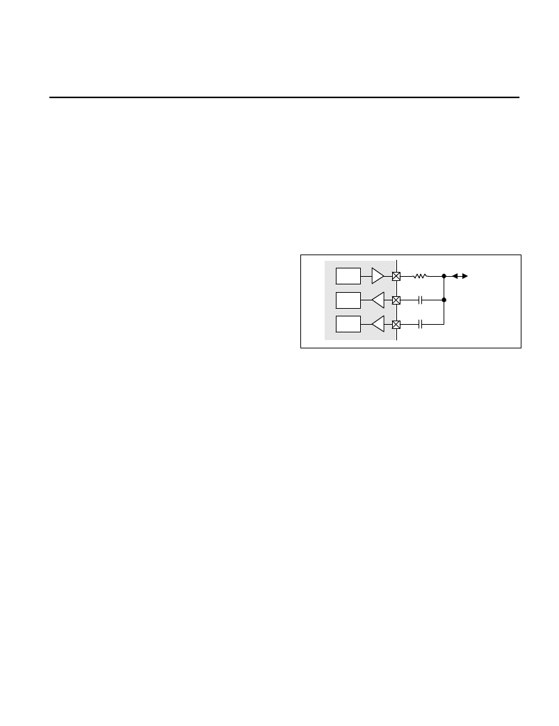
AUXILIARY SVHS OUTPUT MODE
In the SVHS mode, Pin 15 on the auxiliary SCART
connector provides chroma information. To support
this, the auxiliary port on the 5002C includes a
chroma input pin (
Aux_Cin
) that is externally AC
coupled to Pin 15 on the auxiliary SCART connector.
The device also includes an output pin (
Aux_Cout
)
that provides a chroma output to Pin 15 (RED) on
the auxiliary SCART connector. When connected
with the Aux_R and Aux_Cin pins, this forms a bi-
directional port as shown in the following diagram:
Bi-Directional Pin Circuit
Using this configuration, the device will support SVHS
mode for four encoder interface formats. The first
encoder
interface
format
information from the
Enc_C
pin and luma information
from the
Enc_Y
pin. This format is designated “SVHS,
Enc 1”. The second format will receive chroma
information on the
Enc_B
input and luma information
on
Enc_G
. This format is designated "SVHS, Enc 2".
The third format will receive chroma information from
the
Enc_R
pin and luma information from the
Enc_G
pin. This mode is designated “SVHS, Enc 3” on the
serial port register table. For these three modes,
audio will come from the
Lin/Rin
inputs. The fourth
format is designated "SVHS Enc 4". Chroma
information is received on the
Enc2_C
input pin and
the luma is received on the
Enc2_Y
input pin. For this
mode only, audio will come from the
TV_Lin/TV_Rin
inputs.
will
receive
chroma
When the SVHS mode is selected, the DC restore
on the
Aux_Cout
pin will average to approximately
0.9 VDC at the video output load. The DC restore on
the
Aux_YCout
pin will set the blank level to 1.2 V at
the IC pin or approximately 0.6 V across the video
output load.
Mux
Aux_R
Aux_Cout
Aux_Cin
62
Auxiliary
SCART
Pin 15
Mux
Mux
相關PDF資料 |
PDF描述 |
|---|---|
| AX432FM | Adjustable Shunt Regulator |
| AX432FN | Adjustable Shunt Regulator |
| AX432 | Adjustable Shunt Regulator |
| AX432AA | ER 3C 3#8 SKT PLUG |
| AX432AM | Adjustable Shunt Regulator |
相關代理商/技術參數 |
參數描述 |
|---|---|
| AVPro5002R-CGT/F | 功能描述:模擬開關 IC Dual Scart A/V Switch RoHS:否 制造商:Texas Instruments 開關數量:2 開關配置:SPDT 開啟電阻(最大值):0.1 Ohms 切換電壓(最大): 開啟時間(最大值): 關閉時間(最大值): 工作電源電壓:2.7 V to 4.5 V 最大工作溫度:+ 85 C 安裝風格:SMD/SMT 封裝 / 箱體:DSBGA-16 |
| AVPro5002R-CGTR/F | 功能描述:模擬開關 IC Dual Scart A/V Switch RoHS:否 制造商:Texas Instruments 開關數量:2 開關配置:SPDT 開啟電阻(最大值):0.1 Ohms 切換電壓(最大): 開啟時間(最大值): 關閉時間(最大值): 工作電源電壓:2.7 V to 4.5 V 最大工作溫度:+ 85 C 安裝風格:SMD/SMT 封裝 / 箱體:DSBGA-16 |
| AVPro5002R-CM/F | 功能描述:模擬開關 IC Dual Scart A/V Switch RoHS:否 制造商:Texas Instruments 開關數量:2 開關配置:SPDT 開啟電阻(最大值):0.1 Ohms 切換電壓(最大): 開啟時間(最大值): 關閉時間(最大值): 工作電源電壓:2.7 V to 4.5 V 最大工作溫度:+ 85 C 安裝風格:SMD/SMT 封裝 / 箱體:DSBGA-16 |
| AvPRO5002R-DB | 制造商:Maxim Integrated Products 功能描述:Development Boards & Kits - AVR AVPro5002R Demo Brd |
| AVPRO5003 | 制造商:TDK 制造商全稱:TDK Electronics 功能描述:Triple SCART A/V Switch |
發布緊急采購,3分鐘左右您將得到回復。