- 您現(xiàn)在的位置:買賣IC網(wǎng) > Datasheet目錄39 > CAT2300VP2-GT3 (ON Semiconductor)IC SENSE FET CONTROLLER 8TDFN Datasheet資料下載
參數(shù)資料
| 型號: | CAT2300VP2-GT3 |
| 廠商: | ON Semiconductor |
| 文件頁數(shù): | 2/7頁 |
| 文件大小: | 207K |
| 描述: | IC SENSE FET CONTROLLER 8TDFN |
| 標準包裝: | 3,000 |
| 系列: | SENSEFET® |
| 功能: | 電流鏡像 |
| 檢測方法: | 高端 |
| 輸入電壓: | 0.9 V ~ 1.5 V |
| 電流 - 輸出: | 70mA |
| 工作溫度: | -40°C ~ 85°C |
| 安裝類型: | 表面貼裝 |
| 封裝/外殼: | 8-WFDFN 裸露焊盤 |
| 供應(yīng)商設(shè)備封裝: | 8-TDFN(2x3) |
| 包裝: | 帶卷 (TR) |
CAT2300
http://onsemi.com
2
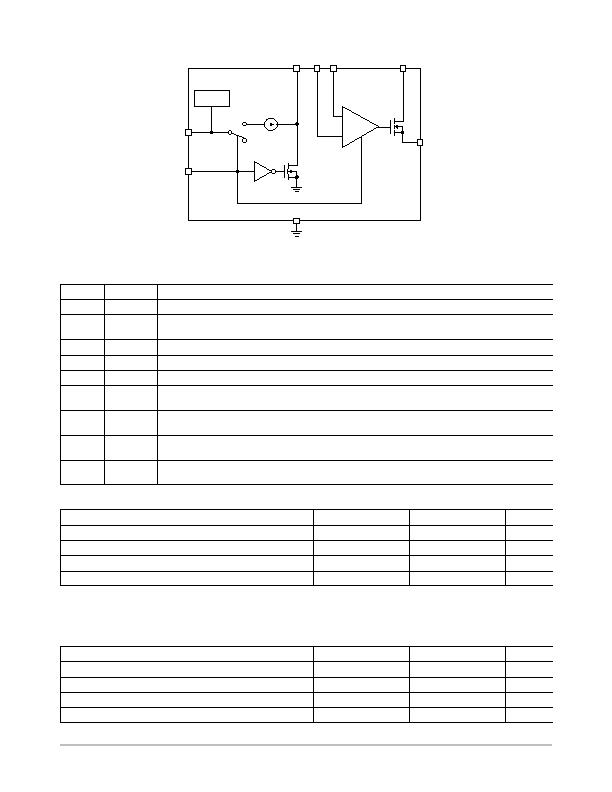
VREG
GND
Sense
KS
Kelvin
Gate
EN
250 mA
1
0
Figure 2. Simplified Block Diagram
I
MEAS
+
V
DD
Table 1. PIN FUNCTION DESCRIPTION
Pin No.
Pin Name
Function
1
Sense
Connects to Sense pin of SENSEFET and directs sensed current to IMEAS output.
2
KS
Kelvin Sense; a Kelvin connection for the current mirror control amplifier. This connection must be made
directly to Sense on the SENSEFET package. Do not share any trace length with CAT2300s Sense lead.
3
Kelvin
Connects to Kelvin pin of the SENSEFET. Serves as the reference point for Sense lead biasing.
4
Gate
Connects to Gate of the SENSEFET and controls SENSEFET operation.
5
GND
Electrical ground for IC.
6
V
DD
External voltage supply for driving the gate of the SENSEFET and power supply for CAT2300 internal
circuitry via an internal voltage regulator.
7
EN
Enable: High true logic input. Turns ON SENSEFET and CAT2300s internal circuitry. A logic LOW on EN
grounds Gate, shutting off the SENSEFET and shuts down the internal current source and mirroring circuitry.
8
I
MEAS
Sensed current output. A resistor between I
MEAS
and ground develops a voltage proportional to the
current flowing through the SENSEFET.
PAD
Backside paddle is internally connected to GND. This pad may be left floating but if connected with PCB it
must be to the ground plane of circuitry which is also grounded.
Table 2. ABSOLUTE MAXIMUM RATINGS (Note 1)
Parameter
Symbol
Value
Unit
V
DD
V
DD
6.5
V
Gate
?5
mA
V
K
, EN, Sense, KS, Kelvin, I
MEAS
6.5
V
Junction Temperature
150
癈
Stresses exceeding Maximum Ratings may damage the device. Maximum Ratings are stress ratings only. Functional operation above the
Recommended Operating Conditions is not implied. Extended exposure to stresses above the Recommended Operating Conditions may affect
device reliability.
1. Guaranteed by design.
Table 3. RECOMMENDED OPERATING CONDITIONS
Parameter
Symbol
Value
Unit
V
K
V
K
0.9 to 1.5
V
V
DD
V
DD
5
V
Maximum Junction Temperature
T
JUNCTION
125
癈
Ambient Temperature Range
T
AMBIENT
40 to +85
癈
相關(guān)PDF資料 |
PDF描述 |
|---|---|
| CAT34TS02VP2GT4A | IC TEMP SENSOR 2K MEMORY 8TDFN |
| CAT6095VP2-GT4 | IC TEMP SENSOR STAND ALONE 8TDFN |
| DS1621S+ | IC THERMOMETER/STAT DIG 8-SOIC |
| DS1624S+T&R | IC THERM/EEPROM DIG 256BYT 8SOIC |
| DS1626S+ | IC THERMOMETER/STAT DIG 8-SOIC |
相關(guān)代理商/技術(shù)參數(shù) |
參數(shù)描述 |
|---|---|
| CAT23SM | 制造商:Nagahori Industry 功能描述:CAT23SM |
| CAT-2-456400-1 | 制造商:Samtec Inc 功能描述:CAT - Bulk |
| CAT24AA01 | 制造商:CATALYST 制造商全稱:Catalyst Semiconductor 功能描述:1-Kb and 2-Kb I2C CMOS Serial EEPROM |
| CAT24AA01TDI-10 | 制造商:CATALYST 制造商全稱:Catalyst Semiconductor 功能描述:1-Kb and 2-Kb I2C CMOS Serial EEPROM |
| CAT24AA01TDI-3 | 制造商:CATALYST 制造商全稱:Catalyst Semiconductor 功能描述:1-Kb and 2-Kb I2C CMOS Serial EEPROM |
發(fā)布緊急采購,3分鐘左右您將得到回復。