- 您現在的位置:買賣IC網 > Datasheet目錄39 > CAT2300VP2-GT3 (ON Semiconductor)IC SENSE FET CONTROLLER 8TDFN Datasheet資料下載
參數資料
| 型號: | CAT2300VP2-GT3 |
| 廠商: | ON Semiconductor |
| 文件頁數: | 4/7頁 |
| 文件大小: | 207K |
| 描述: | IC SENSE FET CONTROLLER 8TDFN |
| 標準包裝: | 3,000 |
| 系列: | SENSEFET® |
| 功能: | 電流鏡像 |
| 檢測方法: | 高端 |
| 輸入電壓: | 0.9 V ~ 1.5 V |
| 電流 - 輸出: | 70mA |
| 工作溫度: | -40°C ~ 85°C |
| 安裝類型: | 表面貼裝 |
| 封裝/外殼: | 8-WFDFN 裸露焊盤 |
| 供應商設備封裝: | 8-TDFN(2x3) |
| 包裝: | 帶卷 (TR) |
CAT2300
http://onsemi.com
4
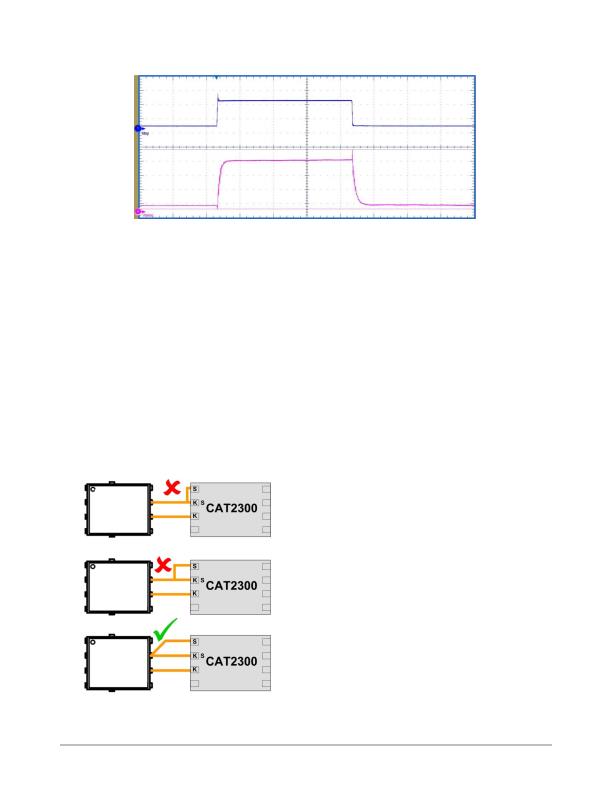
TYPICAL PERFORMANCE CHARACTERISTICS
Figure 3. Load Step: 1 A 10 A
50 ms / div
I
Bus
V
MEAS
PIN DESCRIPTION
Sense
Sense connects directly to the SENSEFETs Sense pin and
directs the sensed current to the I
MEAS
output. Sense is
controlled by an amplifier with a FET follower stage to
maintain Sense at exactly the Kelvin voltage, thus insuring
accuracy of the SENSEFETs mirror current.
KS
KS = Kelvin Sense; a Kelvin connection for the mirroring
amplifier. Current measurement accuracy is dependent upon
the voltage match between the SENSEFETs Sense and
Kelvin leads. To minimize voltage losses in the PCB trace
between CAT2300 and the SENSEFET, a Kelvin connection
for the control amplifier is provided. KS must be a
dedicated connection, shared by no other circuitry, and
tied directly to the Sense pin on of the SENSEFET.
Figure 4. Current Sense
SENSEFET
SENSEFET
SENSEFET
Careful layout is critical in achieving full SENSEFET
perfomance. PCB trace resistance can no longer be ignored
as it can be in typical low current circuit designs. Microvolt
offsets (mV) produce meaningful errors in current ratio
tracking. A few milliohms of trace resistance carrying a few
milliamps of current produces microvolts of potential
difference between CAT2300 and the SENSEFET. To
circumvent this error CAT2300 provides a Kelvin lead (KS)
for monitoring the SENSEFETs Sense pin. Under no
circumstances should the KS connection share any portion
of the current path between the sense pins of CAT2300 and
the SENSEFET. Doing so will degrade measurement
accuracy.
Kelvin
Kelvin connects directly to the SENSEFETs Kelvin pin
and acts the reference voltage for CAT2300s mirroring
circuit. It too must be a dedicated connection, shared by no
other circuitry.
Gate
Gate connects to the SENSEFETs Gate pin and controls
the SENSEFETs operation. Gate is controlled by EN: a
logic 1 turns the SENSEFET ON, a logic 0 turns it OFF.
When ON, voltage is applied to the SENSEFETs gate via
a current source inside CAT2300.
By controlling the gate drive current a controlled turn-ON
is achieved. Faster turn-on times can be done by adding a
supplemental current source to augment the internal current
source. Placing a resistor between V
DD
and Gate will
provide extra current and boost turn-on speeds.
For a softer turn-on characteristic, add capacitance
between the SENSEFETs Gate and Source pins;
approximately 1 nF for every ms of increased delay.
When switching OFF the SENSEFET, Gate provides a
strong pull-down, 7.5 mA typical, so the SENSEFET will be
switched off quickly.
相關PDF資料 |
PDF描述 |
|---|---|
| CAT34TS02VP2GT4A | IC TEMP SENSOR 2K MEMORY 8TDFN |
| CAT6095VP2-GT4 | IC TEMP SENSOR STAND ALONE 8TDFN |
| DS1621S+ | IC THERMOMETER/STAT DIG 8-SOIC |
| DS1624S+T&R | IC THERM/EEPROM DIG 256BYT 8SOIC |
| DS1626S+ | IC THERMOMETER/STAT DIG 8-SOIC |
相關代理商/技術參數 |
參數描述 |
|---|---|
| CAT23SM | 制造商:Nagahori Industry 功能描述:CAT23SM |
| CAT-2-456400-1 | 制造商:Samtec Inc 功能描述:CAT - Bulk |
| CAT24AA01 | 制造商:CATALYST 制造商全稱:Catalyst Semiconductor 功能描述:1-Kb and 2-Kb I2C CMOS Serial EEPROM |
| CAT24AA01TDI-10 | 制造商:CATALYST 制造商全稱:Catalyst Semiconductor 功能描述:1-Kb and 2-Kb I2C CMOS Serial EEPROM |
| CAT24AA01TDI-3 | 制造商:CATALYST 制造商全稱:Catalyst Semiconductor 功能描述:1-Kb and 2-Kb I2C CMOS Serial EEPROM |
發布緊急采購,3分鐘左右您將得到回復。