- 您現在的位置:買賣IC網 > PDF目錄376721 > DIR1701E2K DIGITAL AUDIO INTERFACE RECEIVER PDF資料下載
參數資料
| 型號: | DIR1701E2K |
| 英文描述: | DIGITAL AUDIO INTERFACE RECEIVER |
| 中文描述: | 數字音頻接口接收機 |
| 文件頁數: | 13/19頁 |
| 文件大小: | 290K |
| 代理商: | DIR1701E2K |
DIR1701
SLAS331
–
APRIL 2001
13
www.ti.com
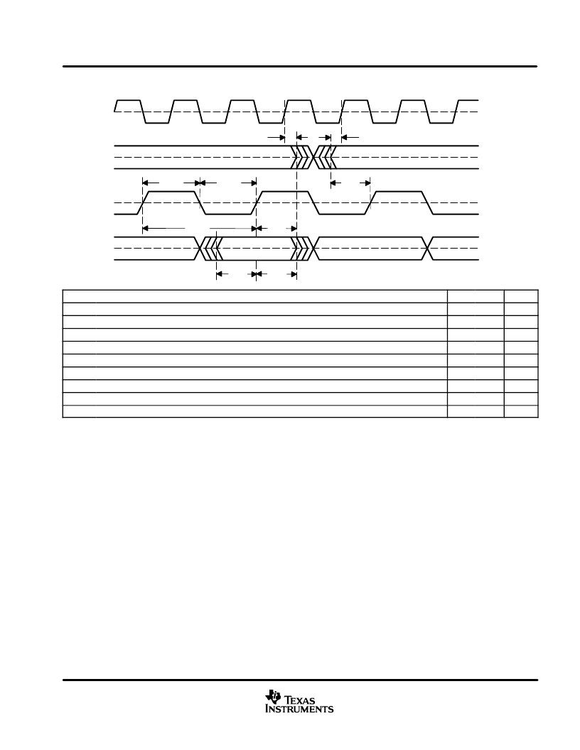
PCM audio interface (continued)
50% of VDD
50% of VDD
50% of VDD
50% of VDD
tSL
tLS
tBCH
tBCL
tLB
tBL
tBCY
tDS
tDH
SCHO
LRCHO
BCHO
DOUT
PARAMETERS
MIN
MAX
UNITS
tSL
tLS
tBCY
tBCL
tBCH
tBL
tLB
tDS
tDH
SCKO rising edge to LRCKO edge
11
ns
LRCKO edge to SCKO rising edge
5
ns
BCKO pulse cycle time
64 fS
BCKO pulse width low
78
ns
BCKO pulse width high
78
ns
BCKO rising edge to LRCKO edge
78
ns
LRCKO edge to BCKO rising edge
78
ns
DOUT setup time
78
ns
DOUT hold time
78
ns
Figure 8. Audio Data Output Timing
dedicated output pins for both professional and consumer applications
The DIR1701 has parallel output pins for both professional and consumer applications. In professional mode
de-emphasis flag EMFLG indicates a 50/15-
μ
s time constant pre-emphasis. Professional mode is set when Bit
0 of CSBIT Byte 0 is HIGH. When Bits 2 to 4 of CSBIT Byte 0 is 110, the EMFLG becomes HIGH. In other cases,
EMFLG is LOW. Audio/non-audio flag ADFLG indicates S/PDIF data mode, i.e., Bit 1 of CSBIT Byte 0. When
ADFLG is LOW, S/PDIF data includes PCM audio signal. In other cases, ADFLG is HIGH.
In consumer mode EMFLG indicates 2-channel audio with a 50/15-
μ
s time constant pre-emphasis. Consumer
mode is set when Bit 0 of CSBIT Byte 0 is LOW. When Bits 3 to 5 of CSBIT Byte 0 is 100, EMFLG becomes
HIGH. In other cases, EMFLG is LOW. The ADFLG signal indicates whether S/PDIF includes digital data, such
as AC-3 or not. When Bit 1 of CSBIT Byte 0 is HIGH, the incoming S/PDIF includes non-audio signal. In other
cases, ADFLG is LOW.
These dedicated output pins are checked for only L-ch CS information. The DIR1701 does not support CRC
check function in professional mode. As for other flags, CS bit and user-bit for professional and consumer
applications, are directly supplied by serial mode at CSBIT (pin 15) and URBIT (pin 16). These pins indicate
L-ch and R-ch information sequentially.
相關PDF資料 |
PDF描述 |
|---|---|
| DIR1701 | DIGITAL AUDIO INTERFACE RECEIVER |
| DIR1701E | DIGITAL AUDIO INTERFACE RECEIVER |
| DIR1703 | DIGITAL AUDIO INTERFACE RECEIVER |
| DIR1703E | DIGITAL AUDIO INTERFACE RECEIVER |
| DISADVANTAGE | Disadvantage of On-Chip Transient Protection (105k) |
相關代理商/技術參數 |
參數描述 |
|---|---|
| DIR1703 | 制造商:TI 制造商全稱:Texas Instruments 功能描述:96-kHz, 24-Bit Digital Audio Interface Receiver |
| DIR1703E | 功能描述:IC DIGTAL AUD INTRFC RCVR 28SSOP RoHS:是 類別:集成電路 (IC) >> 接口 - 驅動器,接收器,收發器 系列:- 標準包裝:1,240 系列:GD 類型:收發器 驅動器/接收器數:3/5 規程:RS232 電源電壓:4.5 V ~ 5.5 V 安裝類型:通孔 封裝/外殼:20-DIP(0.300",7.62mm) 供應商設備封裝:20-PDIP 包裝:管件 |
| DIR1703E/2K | 制造商:Texas Instruments 功能描述:Audio Interface Receiver 28-Pin SSOP T/R 制造商:Texas Instruments 功能描述:AUD INTRFC RCVR 28SSOP - Tape and Reel |
| DIR-600/E | 制造商:D-Link Networks 功能描述: |
發布緊急采購,3分鐘左右您將得到回復。