- 您現在的位置:買賣IC網 > PDF目錄375853 > FM8P51 (Electronic Theatre Controls, Inc.) EPROM/ROM-Based 8-Bit Microcontroller PDF資料下載
參數資料
| 型號: | FM8P51 |
| 廠商: | Electronic Theatre Controls, Inc. |
| 英文描述: | EPROM/ROM-Based 8-Bit Microcontroller |
| 中文描述: | 存儲器/基于ROM的8位微控制器 |
| 文件頁數: | 14/60頁 |
| 文件大小: | 369K |
| 代理商: | FM8P51 |
第1頁第2頁第3頁第4頁第5頁第6頁第7頁第8頁第9頁第10頁第11頁第12頁第13頁當前第14頁第15頁第16頁第17頁第18頁第19頁第20頁第21頁第22頁第23頁第24頁第25頁第26頁第27頁第28頁第29頁第30頁第31頁第32頁第33頁第34頁第35頁第36頁第37頁第38頁第39頁第40頁第41頁第42頁第43頁第44頁第45頁第46頁第47頁第48頁第49頁第50頁第51頁第52頁第53頁第54頁第55頁第56頁第57頁第58頁第59頁第60頁

FM8P51
Rev1.2 Mar 15, 2005
P.14/FM8P51
FEELING
TECHNOLOGY
= 1, A new byte is received while the SPIRCB register is still holding the previous data. In this case, the data
in SPISR register will be ignored and lost.
= 0, Not overflow.
SPION
: SPI module enable bit
= 1, Enable SPI module.
= 0, Disable SPI module.
CKEDG
: Clock edge select bit
= 1, Data shifts out on falling edge of SCK, and shifts in on rising edge of SCK.
= 0, Data shifts in on rising edge of SCK, and shifts in on falling edge of SCK.
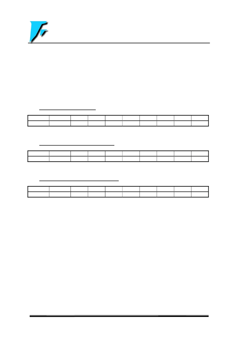
2.1.11 TMR1 (Timer 1 Register) (Bank 0)
Address
Name
B7
B6
0Eh (r/w)
TMR1
TMR17
TMR16
TMR17:TMR10
: Timer 1 register and increase until the value matches to PR1 register, and then reset to “0”.
2.1.12 PR1 (Timer 1 Pulse-width Register) (Bank 0)
Address
Name
B7
B6
B5
0Fh (r/w)
PR1
PR17
PR16
PR15
PR17:PR10
: Timer 1 period register.
2.1.13 T23CON (Timer 2&3 Control Register) (Bank 1)
Address
Name
B7
B6
B5
0Ah (r/w)
T23CON
-
-
-
T2CS
: Timer 2 clock source selection bit
= 1, External clock input T23CKI pin.
= 0, Internal clock Fosc/4.
T2ON
: Timer 2 module enable bit
= 1, Enable Timer 2 module.
= 0, Disable Timer 2 module.
T3CS
: Timer 3 clock source selection bit
= 1, External clock input T23CKI pin.
= 0, Internal clock Fosc/4.
T3ON
: Timer 3 module enable bit
= 1, Enable Timer 3 module.
= 0, Disable Timer 3 module.
T16
:
8-bit or 16-bit timer selection bit for Timer2 & Timer3
= 1, Timer2 & Timer3 are concatenated to form a 16-bit timer.
= 0, Timer2 & Timer3 are two 8-bit incrementing timers.
Bit7:BIT5
: Not used. Read as “0”s
B5
B4
B3
B2
B1
B0
TMR15
TMR14
TMR13
TMR12
TMR11
TMR10
B4
PR14
B3
PR13
B2
PR12
B1
PR11
B0
PR10
B4
T16
B3
T3ON
B2
T3CS
B1
T2ON
B0
T2CS
相關PDF資料 |
PDF描述 |
|---|---|
| FM8P51EF | EPROM/ROM-Based 8-Bit Microcontroller |
| FM8P51EP | EPROM/ROM-Based 8-Bit Microcontroller |
| FM8P51F | EPROM/ROM-Based 8-Bit Microcontroller |
| FM8P51P | EPROM/ROM-Based 8-Bit Microcontroller |
| FM8P51E | EPROM/ROM-Based 8-Bit Microcontroller |
相關代理商/技術參數 |
參數描述 |
|---|---|
| FM8P51E | 制造商:未知廠家 制造商全稱:未知廠家 功能描述:EPROM/ROM-Based 8-Bit Microcontroller |
| FM8P51EF | 制造商:未知廠家 制造商全稱:未知廠家 功能描述:EPROM/ROM-Based 8-Bit Microcontroller |
| FM8P51EP | 制造商:未知廠家 制造商全稱:未知廠家 功能描述:EPROM/ROM-Based 8-Bit Microcontroller |
| FM8P51F | 制造商:未知廠家 制造商全稱:未知廠家 功能描述:EPROM/ROM-Based 8-Bit Microcontroller |
| FM8P51P | 制造商:未知廠家 制造商全稱:未知廠家 功能描述:EPROM/ROM-Based 8-Bit Microcontroller |
發布緊急采購,3分鐘左右您將得到回復。