- 您現在的位置:買賣IC網 > PDF目錄385327 > GS8640Z18GT-200 (GSI TECHNOLOGY) 72Mb Pipelined and Flow Through Synchronous NBT SRAM PDF資料下載
參數資料
| 型號: | GS8640Z18GT-200 |
| 廠商: | GSI TECHNOLOGY |
| 元件分類: | DRAM |
| 英文描述: | 72Mb Pipelined and Flow Through Synchronous NBT SRAM |
| 中文描述: | 4M X 18 ZBT SRAM, 7.5 ns, PQFP100 |
| 封裝: | ROHS COMPLIANT, TQFP-100 |
| 文件頁數: | 6/25頁 |
| 文件大小: | 618K |
| 代理商: | GS8640Z18GT-200 |
GS8640Z18/36T-300/250/200/167
Product Preview
Specifications cited are subject to change without notice. For latest documentation see http://www.gsitechnology.com.
Rev: 1.01 1/2006
6/25
2004, GSI Technology
Functional Details
Clocking
Deassertion of the Clock Enable (CKE) input blocks the Clock input from reaching the RAM's internal circuits. It may be used to
suspend RAM operations. Failure to observe Clock Enable set-up or hold requirements will result in erratic operation.
Pipeline Mode Read and Write Operations
All inputs (with the exception of Output Enable, Linear Burst Order and Sleep) are synchronized to rising clock edges. Single cycle
read and write operations must be initiated with the Advance/Load pin (ADV) held low, in order to load the new address. Device
activation is accomplished by asserting all three of the Chip Enable inputs (E
1
, E
2
and E
3
). Deassertion of any one of the Enable
inputs will deactivate the device.
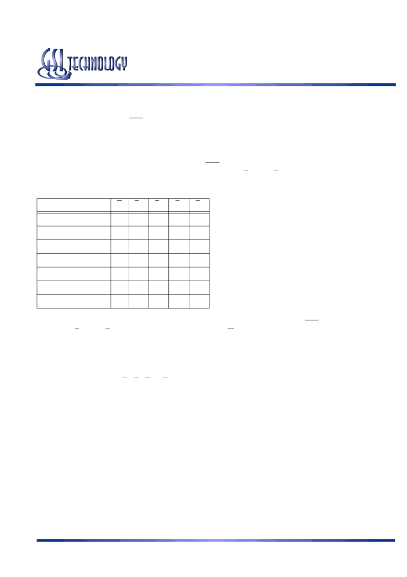
Function
W
B
A
B
B
B
C
B
D
Read
H
X
X
X
X
Write Byte “a”
L
L
H
H
H
Write Byte “b”
L
H
L
H
H
Write Byte “c”
L
H
H
L
H
Write Byte “d”
L
H
H
H
L
Write all Bytes
L
L
L
L
L
Write Abort/NOP
L
H
H
H
H
Read operation is initiated when the following conditions are satisfied at the rising edge of clock: CKE is asserted Low, all three
chip enables (E
1
, E
2,
and E
3
) are active, the write enable input signals W is deasserted high, and ADV is asserted low. The address
presented to the address inputs is latched in to address register and presented to the memory core and control logic. The control
logic determines that a read access is in progress and allows the requested data to propagate to the input of the output register. At
the next rising edge of clock the read data is allowed to propagate through the output register and onto the output pins.
Write operation occurs when the RAM is selected, CKE is active, and the Write input is sampled low at the rising edge of clock.
The Byte Write Enable inputs (B
A
, B
B
, B
C,
& B
D
) determine which bytes will be written. All or none may be activated. A write
cycle with no Byte Write inputs active is a no-op cycle. The pipelined NBT SRAM provides double late write functionality,
matching the write command versus data pipeline length (2 cycles) to the read command versus data pipeline length (2 cycles). At
the first rising edge of clock, Enable, Write, Byte Write(s), and Address are registered. The Data In associated with that address is
required at the third rising edge of clock.
Flow Through Mode Read and Write Operations
Operation of the RAM in Flow Through mode is very similar to operations in Pipeline mode. Activation of a Read Cycle and the
use of the Burst Address Counter is identical. In Flow Through mode the device may begin driving out new data immediately after
new address are clocked into the RAM, rather than holding new data until the following (second) clock edge. Therefore, in Flow
Through mode the read pipeline is one cycle shorter than in Pipeline mode.
Write operations are initiated in the same way, but differ in that the write pipeline is one cycle shorter as well, preserving the ability
to turn the bus from reads to writes without inserting any dead cycles. While the pipelined NBT RAMs implement a double late
write protocol, in Flow Through mode a single late write protocol mode is observed. Therefore, in Flow Through mode, address
and control are registered on the first rising edge of clock and data in is required at the data input pins at the second rising edge of
clock.
相關PDF資料 |
PDF描述 |
|---|---|
| GS8640Z18GT-250 | 72Mb Pipelined and Flow Through Synchronous NBT SRAM |
| GS8640Z18GT-300 | 72Mb Pipelined and Flow Through Synchronous NBT SRAM |
| GS8640Z18T | 72Mb Pipelined and Flow Through Synchronous NBT SRAM |
| GS8640Z18T-167 | 72Mb Pipelined and Flow Through Synchronous NBT SRAM |
| GS8640Z18T-167I | 72Mb Pipelined and Flow Through Synchronous NBT SRAM |
相關代理商/技術參數 |
參數描述 |
|---|---|
| GS8640Z18GT-200I | 制造商:GSI Technology 功能描述:SRAM SYNC QUAD 2.5V/3.3V 72MBIT 4MX18 7.5NS/3NS 100TQFP - Trays 制造商:GSI Technology 功能描述:GTEGS8640Z18GT-200I 4M X 18 (72 MEG) N |
| GS8640Z18GT-200IV | 制造商:GSI Technology 功能描述:SRAM SYNC DUAL 1.8V/2.5V 72MBIT 4MX18 7.5NS/3NS 100TQFP - Trays |
| GS8640Z18GT-200V | 制造商:GSI Technology 功能描述:SRAM SYNC DUAL 1.8V/2.5V 72MBIT 4MX18 7.5NS/3NS 100TQFP - Trays |
| GS8640Z18GT-250 | 制造商:GSI 制造商全稱:GSI Technology 功能描述:72Mb Pipelined and Flow Through Synchronous NBT SRAM |
| GS8640Z18GT-250IV | 制造商:GSI 制造商全稱:GSI Technology 功能描述:72Mb Pipelined and Flow Through Synchronous NBT SRAM |
發布緊急采購,3分鐘左右您將得到回復。