- 您現(xiàn)在的位置:買賣IC網(wǎng) > PDF目錄385354 > HC5523IM (HARRIS SEMICONDUCTOR) LSSGR/TR57 CO/Loop Carrier SLIC with Low Power Standby PDF資料下載
參數(shù)資料
| 型號(hào): | HC5523IM |
| 廠商: | HARRIS SEMICONDUCTOR |
| 元件分類: | 模擬傳輸電路 |
| 英文描述: | LSSGR/TR57 CO/Loop Carrier SLIC with Low Power Standby |
| 中文描述: | TELECOM-SLIC, PQCC28 |
| 文件頁數(shù): | 2/18頁 |
| 文件大小: | 176K |
| 代理商: | HC5523IM |
57
Absolute Maximum Ratings
Thermal Information
Temperature, Humidity
Storage Temperature Range . . . . . . . . . . . . . . . . -65
o
C to 150
o
C
Operating Temperature Range. . . . . . . . . . . . . . . -40
o
C to 110
o
C
Operating Junction Temperature Range. . . . . . . . -40
o
C to 150
o
C
Power Supply (-40
o
C
≤
T
A
≤
85
o
C)
Supply Voltage V
CC
to GND . . . . . . . . . . . . . . . . . . . . 0.5V to 7V
Supply Voltage V
EE
to GND. . . . . . . . . . . . . . . . . . . . .-7V to 0.5V
Supply Voltage V
BAT
to GND. . . . . . . . . . . . . . . . . . .-80V to 0.5V
Ground
Voltage between AGND and BGND. . . . . . . . . . . . . -0.3V to 0.3V
Relay Driver
Ring Relay Supply Voltage . . . . . . . . . . . . . . . . 0V to V
BAT
+75V
Ring Relay Current. . . . . . . . . . . . . . . . . . . . . . . . . . . . . . . . 50mA
Ring Trip Comparator
Input Voltage . . . . . . . . . . . . . . . . . . . . . . . . . . . . . . . . V
BAT
to 0V
Input Current . . . . . . . . . . . . . . . . . . . . . . . . . . . . . . -5mA to 5mA
Digital Inputs, Outputs (C1, C2, E0, E1, DET)
Input Voltage . . . . . . . . . . . . . . . . . . . . . . . . . . . . . . . . .0V to V
CC
Output Voltage (DET Not Active) . . . . . . . . . . . . . . . . . .0V to V
CC
Output Current (DET). . . . . . . . . . . . . . . . . . . . . . . . . . . . . . . 5mA
Tipx and Ringx Terminals (-40
o
C
≤
T
A
≤
+85
o
C)
Tipx or Ringx Voltage, Continuous (Referenced to GND)V
BAT
to +2V
Tipx or Ringx, Pulse < 10ms, T
REP
> 10s . . . . V
BAT
-20V to +5V
Tipx or Ringx, Pulse < 10
μ
s, T
REP
> 10s . . . V
BAT
-40V to +10V
Tipx or Ringx, Pulse < 250ns, T
REP
> 10s. . . V
BAT
-70V to +15V
Tipx or Ringx Current. . . . . . . . . . . . . . . . . . . . . . . . . . . . . . 70mA
ESD Rating . . . . . . . . . . . . . . . . . . . . . . . . . . . . . . . . . . . . . . . .500V
Thermal Resistance (Typical, Note 1)
22 Lead PDIP Package . . . . . . . . . . . . . . . . . . . . . . .
28 Lead PLCC Package. . . . . . . . . . . . . . . . . . . . . . .
Continuous Power Dissipation at 70
o
C
22 Lead PDIP Package. . . . . . . . . . . . . . . . . . . . . . . . . . . . .1.5W
28 Lead PLCC Package . . . . . . . . . . . . . . . . . . . . . . . . . . . .1.5W
Package Power Dissipation at 70
o
C, t < 100ms, t
REP
> 1s
22 Lead PDIP Package. . . . . . . . . . . . . . . . . . . . . . . . . . . . . . 4W
28 Lead PLCC Package . . . . . . . . . . . . . . . . . . . . . . . . . . . . . 4W
Derate above . . . . . . . . . . . . . . . . . . . . . . . . . . . . . . . . . . . . . . .70
o
C
Plastic DIP . . . . . . . . . . . . . . . . . . . . . . . . . . . . . . . . . 18.8mW/
o
C
PLCC . . . . . . . . . . . . . . . . . . . . . . . . . . . . . . . . . . . . . 18.8mW/
o
C
Maximum Junction Temperature Range . . . . . . . . . -40
o
C to 150
o
C
Maximum Storage Temeprature Range. . . . . . . . . . -65
o
C to 150
o
C
Maximum Lead Temperature. . . . . . . . . . . . . . . . . . . . . . . . . .300
o
C
(Soldering 10s, PLCC Lead Tips Only)
θ
JA
53
o
C/W
53
o
C/W
Die Characteristics
Gate Count . . . . . . . . . . . . . . . . . . . . . . .543 Transistors, 51 Diodes
CAUTION: Stresses above those listed in “Absolute Maximum Ratings” may cause permanent damage to the device. This is a stress only rating and operation of the
device at these or any other conditions above those indicated in the operational sections of this specification is not implied.
NOTE:
1.
θ
JA
is measured with the component mounted on an evaluation PC board in free air.
Typical Operating Conditions
These represent the conditions under which the part was developed and are suggested as guidelines.
PARAMETER
CONDITIONS
MIN
TYP
MAX
UNITS
o
C
Case Temperature
-40
-
100
V
CC
with Respect to AGND
V
EE
with Respect to AGND
V
BAT
with Respect to BGND
-40
o
C to 85
o
C
-40
o
C to 85
o
C
-40
o
C to 85
o
C
4.75
-
5.25
V
-5.25
-
-4.75
V
-58
-
-24
V
Electrical Specifications
T
A
= -40
o
C to 85
o
C, V
CC
= +5V
±
5%, V
EE
= -5V
±
5%, V
BAT
= -48V, AGND = BGND = 0V, R
DC1
= R
DC2
= 41.2k
,
R
D
= 39k
, R
SG
= 0
, R
F1
= R
F2
= 0
, C
HP
= 10nF, C
DC
= 1.5
μ
F, Z
L
= 600
, Unless Otherwise Specified. All pin
number references in the figures refer to the 28 lead PLCC package.
PARAMETER
CONDITIONS
MIN
TYP
MAX
UNITS
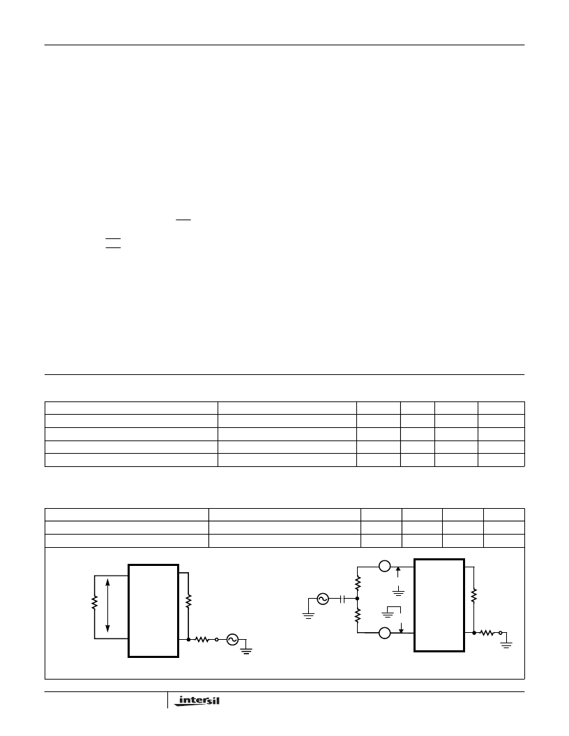
Overload Level
1% THD, Z
L
= 600
, (Note 2, Figure 1)
0 < f < 100Hz (Note 3, Figure 2)
3.1
-
-
V
PEAK
/Wire
Longitudinal Impedance (Tip/Ring)
-
20
35
FIGURE 1. OVERLOAD LEVEL (TWO-WIRE PORT)
FIGURE 2. LONGITUDINAL IMPEDANCE
TIP
27
V
TX
19
RING
28
RSN
16
I
DCMET
23mA
R
T
600k
R
RX
E
RX
R
L
V
TRO
300k
600
E
L
V
T
C
0 < f < 100Hz
V
R
LZ
T
= V
T
/A
T
LZ
R
= V
R
/A
R
1V
RMS
300
300
2.16
μ
F
TIP
27
V
TX
19
RING
28
RSN
16
R
T
600k
R
RX
300k
A
T
A
R
HC5523
相關(guān)PDF資料 |
PDF描述 |
|---|---|
| HC5523IP | LSSGR/TR57 CO/Loop Carrier SLIC with Low Power Standby |
| HC5526CM | ITU CO/PABX SLIC with Low Power Standby |
| HC5526CP | ITU CO/PABX SLIC with Low Power Standby |
| HC5526IM | ITU CO/PABX SLIC with Low Power Standby |
| HC5526IP | ITU CO/PABX SLIC with Low Power Standby |
相關(guān)代理商/技術(shù)參數(shù) |
參數(shù)描述 |
|---|---|
| HC5523IMR4722 | 制造商:Rochester Electronics LLC 功能描述:- Bulk |
| HC5523IMX6176C | 制造商:Rochester Electronics LLC 功能描述:- Bulk |
| HC5523IP | 制造商:Rochester Electronics LLC 功能描述:- Bulk |
| HC-5524 | 制造商:INTERSIL 制造商全稱:Intersil Corporation 功能描述:EIA/ITU 24V PABX SLIC with 25mA Loop Feed |
| HC5526 | 制造商:INTERSIL 制造商全稱:Intersil Corporation 功能描述:ITU CO/PABX SLIC with Low Power Standby |
發(fā)布緊急采購,3分鐘左右您將得到回復(fù)。