- 您現在的位置:買賣IC網 > PDF目錄385354 > HC5523IM (HARRIS SEMICONDUCTOR) LSSGR/TR57 CO/Loop Carrier SLIC with Low Power Standby PDF資料下載
參數資料
| 型號: | HC5523IM |
| 廠商: | HARRIS SEMICONDUCTOR |
| 元件分類: | 模擬傳輸電路 |
| 英文描述: | LSSGR/TR57 CO/Loop Carrier SLIC with Low Power Standby |
| 中文描述: | TELECOM-SLIC, PQCC28 |
| 文件頁數: | 9/18頁 |
| 文件大小: | 176K |
| 代理商: | HC5523IM |
64
The value of R
SG
should be calculated to allow maximum
loop length operation. This requires that the saturation guard
reference voltage be set as high as possible without clipping
the incoming or outgoing VF signal. A voltage margin of -4V
on tip and -4V on ring, for a total of -8V margin, is
recommended as a general guideline. The value of R
SG
is
calculated using Equation 6:
where:
V
BAT
= Battery voltage.
V
MAR
= Voltage Margin. Recommended value of -8V to
allow a maximum overload level of 3.1V peak.
For on-hook transmission R
L
=
∞
, Equation 6 reduces to:
5
BAT
SLIC in the Standby Mode
Overall system power is saved by configuring the SLIC in the
standby state when not in use. In the standby state the tip and
ringamplifiersaredisabledandinternalresistorsareconnected
between tip to ground and ring to V
BAT
. This connection
enables a loop current to flow when the phone goes off-hook.
The loop current detector then detects this current and the
SLIC is configured in the active mode for voice transmission.
The loop current in standby state is calculated as follows:
where:
I
L
= Loop current in the standby state.
R
L
= Loop resistance.
V
BAT
= Battery voltage.
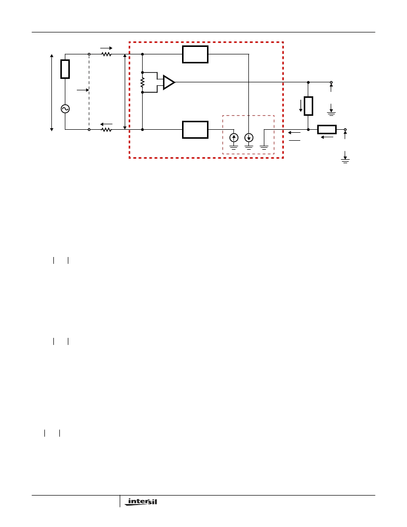
(AC) Transmission Path
SLIC in the Active Mode
Figure 16 shows a simplified AC transmission model. Circuit
analysis yields the following design equations:
where:
V
TR
= Is the AC metallic voltage between tip and ring,
including the voltage drop across the fuse resistors R
F
.
V
TX
= Is the AC metallic voltage. Either at the ground
referenced 4-wire side or the SLIC tip and ring terminals.
I
M
= Is the AC metallic current.
R
F
= Is a fuse resistor.
Z
T
= Is used to set the SLIC’s 2-wire impedance.
V
RX
= Is the analog ground referenced receive signal.
Z
RX
= Is used to set the 4-wire to 2-wire gain.
E
G
= Is the AC open circuit voltage.
Z
L
= Is the line impedance.
(AC) 2-Wire Impedance
The AC 2-wire impedance (Z
TR
) is the impedance looking
into the SLIC, including the fuse resistors, and is calculated
as follows:
Let V
RX
= 0. Then from Equation 10
RSG
---------------------------------------------
VBAT
VMAR
–
(
)
1
)
+
16.66V
–
×
----------------------------------------------------------------------------------------+
17300
–
=
(EQ. 6)
R
SG
MAR
------------------–
17300
–
=
(EQ. 7)
I
L
V
L
3V
–
---------+
≈
(EQ. 8)
V
TR
V
TX
I
M
2R
F
+
=
(EQ. 9)
V
T
----------
V
RX
-----------
+
I
------------
=
(EQ. 10)
V
TR
E
G
I
M
Z
L
–
=
(EQ. 11)
V
TX
RSN
TIP
RING
I
M
1000
Z
TR
V
TR
E
G
-
V
TX
I
M
V
TX
Z
RX
1
HC5523
R
F
R
F
A = 4
+
-
+
-
+
+
-
Z
T
+
-
V
RX
+
-
A = 250
A = 250
I
M
Z
L
FIGURE 16. SIMPLIFIED AC TRANSMISSION CIRCUIT
V
TX
Z
T
I
------------
=
(EQ. 12)
HC5523
相關PDF資料 |
PDF描述 |
|---|---|
| HC5523IP | LSSGR/TR57 CO/Loop Carrier SLIC with Low Power Standby |
| HC5526CM | ITU CO/PABX SLIC with Low Power Standby |
| HC5526CP | ITU CO/PABX SLIC with Low Power Standby |
| HC5526IM | ITU CO/PABX SLIC with Low Power Standby |
| HC5526IP | ITU CO/PABX SLIC with Low Power Standby |
相關代理商/技術參數 |
參數描述 |
|---|---|
| HC5523IMR4722 | 制造商:Rochester Electronics LLC 功能描述:- Bulk |
| HC5523IMX6176C | 制造商:Rochester Electronics LLC 功能描述:- Bulk |
| HC5523IP | 制造商:Rochester Electronics LLC 功能描述:- Bulk |
| HC-5524 | 制造商:INTERSIL 制造商全稱:Intersil Corporation 功能描述:EIA/ITU 24V PABX SLIC with 25mA Loop Feed |
| HC5526 | 制造商:INTERSIL 制造商全稱:Intersil Corporation 功能描述:ITU CO/PABX SLIC with Low Power Standby |
發布緊急采購,3分鐘左右您將得到回復。