- 您現(xiàn)在的位置:買賣IC網(wǎng) > PDF目錄385355 > HC5549CM (HARRIS SEMICONDUCTOR) Low Power SLIC with Battery Switch PDF資料下載
參數(shù)資料
| 型號: | HC5549CM |
| 廠商: | HARRIS SEMICONDUCTOR |
| 元件分類: | 模擬傳輸電路 |
| 英文描述: | Low Power SLIC with Battery Switch |
| 中文描述: | TELECOM-SLIC, PQCC28 |
| 文件頁數(shù): | 7/13頁 |
| 文件大小: | 87K |
| 代理商: | HC5549CM |
4-86
Forward Active
Overview
The forward active mode (FA, 001) is the primary AC
transmission mode of the device. On hook transmission, DC
loop feed and voice transmission are supported during forward
active. Loop supervision is provided by either the switch hook
detector (E0 = 1) or the ground key detector (E0 = 0). The
device may be operated from either high or low battery for on-
hook transmission and low battery for loop feed.
On-Hook Transmission
The primary purpose of on hook transmission will be to
support caller ID and other advanced signalling features.
The transmission over load level while on hook is 3.5V
PEAK
.
When operating from the high battery, the DC voltages at Tip
and Ring are MTU compliant. The typical Tip voltage is -4V
and the Ring voltage is a function of the battery voltage for
battery voltages less than -60V as shown in Equation 17.
Loop supervision is provided by the switch hook detector at
the DET output. When DET goes low, the low battery should
be selected for DC loop feed and voice transmission.
Feed Architecture
The design implements a voltage feed current sense
architecture. The device controls the voltage across Tip and
Ring based on the sensing of load current. Resistors are
placed in series with Tip and Ring outputs to provide the
current sensing. The diagram below illustrates the concept.
R
B
By monitoring the current at the amplifier output, a negative
feedback mechanism sets the output voltage for a defined
load. The amplifier gains are set by resistor ratios (R
A
, R
B
,
R
C
) providing all the performance benefits of matched
resistors. The internal sense resistor, R
CS
, is much smaller
than the gain resistors and is typically 20
for this device.
The feedback mechanism, K
S
, represents the amplifier
configuration providing the negative feedback.
DC Loop Feed
The feedback mechanism for monitoring the DC portion of
the loop current is the loop detector. A low pass filter is used
in the feedback to block voice band signals from interfering
with the loop current limit function. The pole of the low pass
filter is set by the external capacitor C
DC
. The value of the
external capacitor should be 4.7
μ
F.
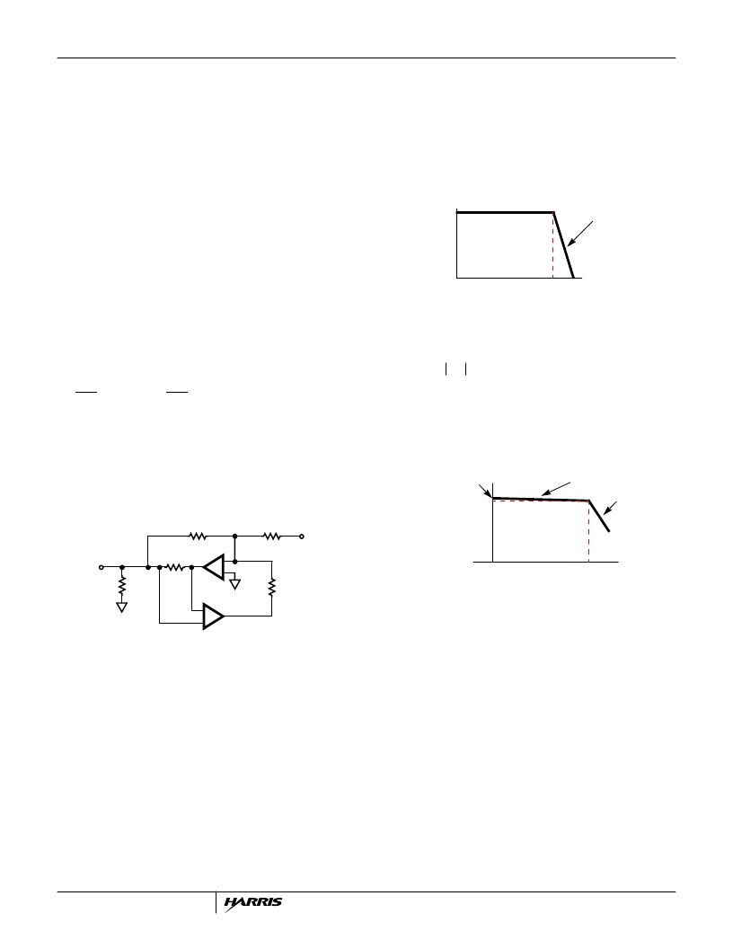
Most applications will operate the device from low battery
while off hook. The DC feed characteristic of the device will
drive Tip and Ring towards half battery to regulate the DC
loop current. For light loads, Tip will be near -4V and Ring
will be near V
VBL
+ 4V. The following diagram shows the DC
feed characteristic.
The point on the y-axis labeled V
TR(OC)
is the open circuit
Tip to Ring voltage and is defined by the feed battery
voltage.
The curve of Figure 5 determines the actual loop current for
a given set of loop conditions. The loop conditions are
determined by the low battery voltage and the DC loop
impedance. The DC loop impedance is the sum of the
protection resistance, copper resistance (ohms/foot) and the
telephone off hook DC resistance.
I
SC
The slope of the feed characteristic and the battery voltage
define the maximum loop current on the shortest possible
loop as the short circuit current I
SC
.
V
The term I
LIM
is the programmed current limit, 1760/R
IL
.
The line segment I
A
represents the constant current region
of the loop current limit function.
The maximum loop impedance for a programmed loop
current is defined as R
KNEE
.
V
)
LIM
V
RING
V
BH
4
+
=
(EQ. 17)
FIGURE 3. VOLTAGE FEED CURRENT SENSE DIAGRAM
+
-
+
-
V
IN
V
OUT
R
C
R
CS
R
L
R
A
K
S
FIGURE 4. DC FEED CHARACTERISTIC
m = (
V
TR
/
I
L
) = 10k
I
LOOP
(mA)
I
LIM
V
TR(OC)
V
T
,
V
TR OC
)
V
BL
8
–
=
(EQ. 18)
FIGURE 5. I
LOOP
VERSUS R
LOOP
LOAD CHARACTERISTIC
R
LOOP
(
)
R
KNEE
I
LIM
I
L
I
A
I
B
2R
P
I
SC
I
LIM
2R
I
–
-----------------------------------------------------
+
=
(EQ. 19)
I
A
I
LIM
V
--------------------------------------------------------------
R
I
–
+
=
(EQ. 20)
R
KNEE
-----------------------
=
(EQ. 21)
HC5549
相關PDF資料 |
PDF描述 |
|---|---|
| HC5549IM | THERMISTOR PTC1KOHM 70 DEG 0805 |
| HC5549 | Low Power SLIC with Battery Switch(用戶線接口電路) |
| HC573 | Octal 3-State Noninverting Transparent Latch(High-Performance Silicon-Gate CMOS) |
| HC595 | 8-Bit Serial-Input/Serial or Parallel-Output Shift Register with Latched 3-State Outputs |
| HC652 | EPROM IC; Memory Size:128Kbit; Memory Configuration:16K x 8; Access Time, Tacc:250ns; Package/Case:28-DIP; EPROM Type:Parallel UV Erasable; Supply Voltage Nom, Vcc:5V; Mounting Type:Through Hole; Voltage Rating:5V |
相關代理商/技術參數(shù) |
參數(shù)描述 |
|---|---|
| HC5549CMZ | 制造商:Intersil Corporation 功能描述:SLIC 1CH 59DB 45MA 5V 28PLCC - Rail/Tube |
| HC5549IM | 制造商:INTERSIL 制造商全稱:Intersil Corporation 功能描述:Low Power SLIC with Battery Switch |
| HC5552 | 制造商:未知廠家 制造商全稱:未知廠家 功能描述:Telecommunication IC |
| HC5553 | 制造商:未知廠家 制造商全稱:未知廠家 功能描述:Telecommunication IC |
| HC-55536 | 制造商:INTERSIL 制造商全稱:Intersil Corporation 功能描述:Continuously Variable Slope Delta-Demodulator (CVSD) |
發(fā)布緊急采購,3分鐘左右您將得到回復。