- 您現在的位置:買賣IC網 > PDF目錄385388 > HMP8117CN (INTERSIL CORP) NTSC/PAL Video Decoder PDF資料下載
參數資料
| 型號: | HMP8117CN |
| 廠商: | INTERSIL CORP |
| 元件分類: | 顏色信號轉換 |
| 英文描述: | NTSC/PAL Video Decoder |
| 中文描述: | COLOR SIGNAL DECODER, PDSO80 |
| 封裝: | PLASTIC, MS-022GB-1, MQFP-80 |
| 文件頁數: | 23/45頁 |
| 文件大小: | 269K |
| 代理商: | HMP8117CN |
第1頁第2頁第3頁第4頁第5頁第6頁第7頁第8頁第9頁第10頁第11頁第12頁第13頁第14頁第15頁第16頁第17頁第18頁第19頁第20頁第21頁第22頁當前第23頁第24頁第25頁第26頁第27頁第28頁第29頁第30頁第31頁第32頁第33頁第34頁第35頁第36頁第37頁第38頁第39頁第40頁第41頁第42頁第43頁第44頁第45頁
23
1B
H
1C
H
1D
H
1E
H
1F
H
Saturation
80
H
40
H
80
H
10
H
00
H
80
H
00
H
Color Gain Adjust
Video Gain Adjust
Sharpness
Host Control
Set bit 7 for Soft Reset. Set bit 6 for Power Down.
20
H
-23
H
24
H
-29
H
31
H
/30
H
32
H
34
H
/33
H
35
H
36
H
37
H
41
H
42
H
50
H
51
H
52
H
53
H
7F
H
Sub-Addresses: 40
H
, 43
H
-4F
H
are reserved. Reads from these registers may return non-zero values.
Sub-Addresses: 07
H
, 09
H
, 0D
H
, 2A
H
-2F
H
, 38
H
-3F
H
and 54
H
-7E
H
are unused. Reads from these registers return 00
H
. Writes are ignored.
Closed Caption Data Registers
WSS Data & CRC Registers
Start H_BLANK MSB/LSB
03
H
/4A
H
7A
H
01
H
/02
H
12
H
30
H
20
H
26
H
00
H
0C
H
14
H
02
H
00
H
01
H
Table 3
BLANK programming changes for each video standard.
End H_BLANK
Table 3
(same as above)
Start V_BLANK MSB/LSB
Table 3
(same as above)
End V_BLANK
Table 3
(same as above)
End HSYNC
Table 3
(same as above)
HSYNC Detect Window
90
H
A wider window tolerates poorly timed video sources.
MV Control
Reserved
30
H
21
H
Set bits 5-4 to 11
B
for optimum performance.
A slower PFG improves AGC stability.
Programmable Fractional Gain
MV Stripe Gate
Reserved
22
H
F0
H
Set bit 5 to “1” for optimum performance.
AGC Hysteresis
Larger hysteresis improves AGC stability.
Device Revision
Production baseline revision is 01
H
.
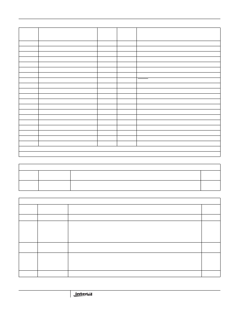
TABLE 10. CONTROL REGISTER SUMMARY (Continued)
SUB-
ADDRESS
CONTROL REGISTER
RESET/
DEFAULT
VALUE
USE
VALUE
COMMENTS
TABLE 11. PRODUCT ID REGISTER
SUB ADDRESS = 00
H
BIT
NUMBER
FUNCTION
DESCRIPTION
RESET
STATE
7-0
Product ID
This 8-bit register specifies the last two digits of the product number. Data written to this read-
only register is ignored.
17
H
TABLE 12. INPUT FORMAT REGISTER.
SUB ADDRESS = 01
H
BIT
NUMBER
FUNCTION
DESCRIPTION
RESET
STATE
7
Reserved
0
B
6-5
Video Timing
Standard
These bits are read only unless bit 4 = “0”.
00 = (M) NTSC
01 = (B, D, G, H, I, N) PAL
10 = (M) PAL
11 = Combination (N) PAL; also called (N
C
) PAL
00
B
4
Auto Detect
Video Standard
0 = Manual selection of video timing standard
1 = Auto detect of video timing standard
1
B
3
Setup Select
Typically, this bit should be a “1” during (M) NTSC and (M, N) PAL operation. Otherwise, it should
be a “0”.
0 = Video source has a 0 IRE blanking pedestal
1 = Video source has a 7.5 IRE blanking pedestal
1
B
2-1
Reserved
00
B
HMP8117
相關PDF資料 |
PDF描述 |
|---|---|
| HMP8154 | NTSC/PAL Encoders |
| HMP8154CN | NTSC/PAL Encoders |
| HMP8156A | NTSC/PAL Encoders |
| HMP8154EVAL1 | NTSC/PAL Encoders |
| HMP8190 | NTSC/PAL Video Encoder |
相關代理商/技術參數 |
參數描述 |
|---|---|
| HMP8117CN96 | 制造商:Rochester Electronics LLC 功能描述:- Bulk |
| HMP8117CNZ | 功能描述:編碼器、解碼器、復用器和解復用器 W/ANNEAL 80PQFP 0+70 DECODER W/MA RoHS:否 制造商:Micrel 產品:Multiplexers 邏輯系列:CMOS 位數: 線路數量(輸入/輸出):2 / 12 傳播延遲時間:350 ps, 400 ps 電源電壓-最大:2.625 V, 3.6 V 電源電壓-最小:2.375 V, 3 V 最大工作溫度:+ 85 C 安裝風格:SMD/SMT 封裝 / 箱體:QFN-44 封裝:Tray |
| HMP8154 | 制造商:INTERSIL 制造商全稱:Intersil Corporation 功能描述:NTSC/PAL Encoders |
| HMP8154_05 | 制造商:INTERSIL 制造商全稱:Intersil Corporation 功能描述:NTSC/PAL Encoders |
| HMP8154CN | 制造商:Rochester Electronics LLC 功能描述:- Bulk |
發布緊急采購,3分鐘左右您將得到回復。