- 您現在的位置:買賣IC網 > PDF目錄385441 > IRF6716MPBF (International Rectifier) DirectFET Power MOSFET PDF資料下載
參數資料
| 型號: | IRF6716MPBF |
| 廠商: | International Rectifier |
| 英文描述: | DirectFET Power MOSFET |
| 中文描述: | DirectFET功率MOSFET |
| 文件頁數: | 1/9頁 |
| 文件大小: | 648K |
| 代理商: | IRF6716MPBF |
www.irf.com
1
02/20/07
IRF6716MPbF
IRF6716MTRPbF
DirectFET
Power MOSFET
Applicable DirectFET Outline and Substrate Outline (see p.7,8 for details)
SQ
SX
ST
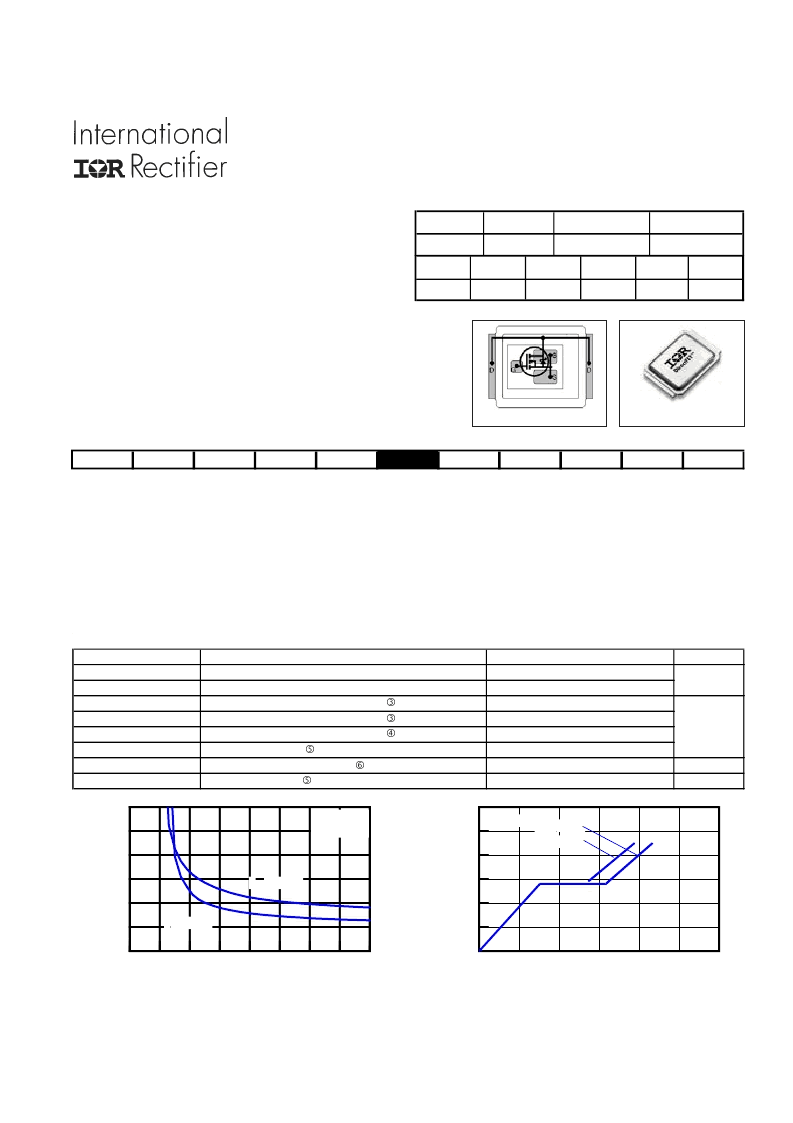
Fig 1.
Typical On-Resistance vs. Gate Voltage
Fig 2.
Typical Total Gate Charge vs Gate-to-Source Voltage
RoHs Compliant Containing No Lead and Bromide
Low Profile (<0.6 mm)
Dual Sided Cooling Compatible
Ultra Low Package Inductance
Optimized for High Frequency Switching
Ideal for CPU Core DC-DC Converters
Optimized for Sync. FET socket of Sync. Buck Converter
Low Conduction and Switching Losses
Compatible with existing Surface Mount Techniques
100% Rg tested
Click on this section to link to the appropriate technical paper.
Click on this section to link to the DirectFET Website.
Surface mounted on 1 in. square Cu board, steady state.
T
C
measured with thermocouple mounted to top (Drain) of part.
Repetitive rating; pulse width limited by max. junction temperature.
Starting T
J
= 25°C, L = 0.65mH, R
G
= 25
, I
AS
= 32A.
DirectFET
ISOMETRIC
Description
The IRF6716MPbF combines the latest HEXFET Power MOSFET Silicon technology with the advanced DirectFET
TM
packaging to achieve
the lowest on-state resistance in a package that has the footprint of a SO-8 and only 0.6 mm profile. The DirectFET package is compatible
with existing layout geometries used in power applications, PCB assembly equipment and vapor phase, infra-red or convection soldering
techniques, when application note AN-1035 is followed regarding the manufacturing methods and processes. The DirectFET package allows
dual sided cooling to maximize thermal transfer in power systems, improving previous best thermal resistance by 80%.
The IRF6716MPbF balances both low resistance and low charge along with ultra low package inductance to reduce both conduction and
switching losses. The reduced total losses make this product ideal for high efficiency DC-DC converters that power the latest generation of
processors operating at higher frequencies. The IRF6716MPbF has been optimized for parameters that are critical in synchronous buck
including Rds(on), gate charge and Cdv/dt-induced turn on immunity. The IRF6716MPbF offers particularly low Rds(on) and high Cdv/dt
immunity for synchronous FET applications
.
Absolute Maximum Ratings
Parameter
V
DS
Drain-to-Source Voltage
V
GS
Gate-to-Source Voltage
I
D
@ T
A
= 25°C
Continuous Drain Current, V
GS
@ 10V
I
D
@ T
A
= 70°C
Continuous Drain Current, V
GS
@ 10V
I
D
@ T
C
= 25°C
Continuous Drain Current, V
GS
@ 10V
I
DM
Pulsed Drain Current
E
AS
Single Pulse Avalanche Energy
I
AR
Avalanche Current
MQ
MX
MT
MP
0
10
20
30
40
50
60
QG Total Gate Charge (nC)
0.0
1.0
2.0
3.0
4.0
5.0
6.0
VG
VDS= 20V
VDS= 13V
ID= 32A
Units
V
A
mJ
A
32
Max.
25
31
180
320
330
±20
39
V
DSS
25V max
Q
g tot
39nC
V
GS
R
DS(on)
1.2m
@10V
Q
gs2
5.3nC
R
DS(on)
2.0m
@ 4.5V
Q
oss
V
gs(th)
27nC
±20V max
Q
gd
12nC
Q
rr
28nC
1.9V
2
3
4
5
6
7
8
9
10
VGS, Gate -to -Source Voltage (V)
0
1
2
3
4
5
6
T(
)
ID = 40A
TJ = 25°C
TJ = 125°C
相關PDF資料 |
PDF描述 |
|---|---|
| IRF6716MTRPbF | DirectFET Power MOSFET |
| IRF6726MPBF | DirectFET Power MOSFET |
| IRF6726MTRPbF | DirectFET Power MOSFET |
| IRF6727MPBF | DirectFET Power MOSFET |
| IRF6727MTRPbF | DirectFET Power MOSFET |
相關代理商/技術參數 |
參數描述 |
|---|---|
| IRF6716MPBF_09 | 制造商:IRF 制造商全稱:International Rectifier 功能描述:DirectFETPower MOSFET |
| IRF6716MTR1PBF | 功能描述:MOSFET 25V 1 N-CH HEXFET 1.6mOhms 39nC RoHS:否 制造商:STMicroelectronics 晶體管極性:N-Channel 汲極/源極擊穿電壓:650 V 閘/源擊穿電壓:25 V 漏極連續電流:130 A 電阻汲極/源極 RDS(導通):0.014 Ohms 配置:Single 最大工作溫度: 安裝風格:Through Hole 封裝 / 箱體:Max247 封裝:Tube |
| IRF6716MTRPBF | 功能描述:MOSFET 25V 1 N-CH HEXFET 1.6mOhms 39nC RoHS:否 制造商:STMicroelectronics 晶體管極性:N-Channel 汲極/源極擊穿電壓:650 V 閘/源擊穿電壓:25 V 漏極連續電流:130 A 電阻汲極/源極 RDS(導通):0.014 Ohms 配置:Single 最大工作溫度: 安裝風格:Through Hole 封裝 / 箱體:Max247 封裝:Tube |
| IRF6717MPBF | 制造商:IRF 制造商全稱:International Rectifier 功能描述:DirectFETPower MOSFET |
| IRF6717MTR1PBF | 功能描述:MOSFET 25V 1 N-CH HEXFET 1.25mOhms 46nC RoHS:否 制造商:STMicroelectronics 晶體管極性:N-Channel 汲極/源極擊穿電壓:650 V 閘/源擊穿電壓:25 V 漏極連續電流:130 A 電阻汲極/源極 RDS(導通):0.014 Ohms 配置:Single 最大工作溫度: 安裝風格:Through Hole 封裝 / 箱體:Max247 封裝:Tube |
發布緊急采購,3分鐘左右您將得到回復。