- 您現在的位置:買賣IC網 > PDF目錄360994 > ISDMICROTAD-16M PDF資料下載
參數資料
| 型號: | ISDMICROTAD-16M |
| 文件頁數: | 6/26頁 |
| 文件大小: | 1522K |
| 代理商: | ISDMICROTAD-16M |
ISD MicroTAD-16M
4
Voice Solutions in Silicon
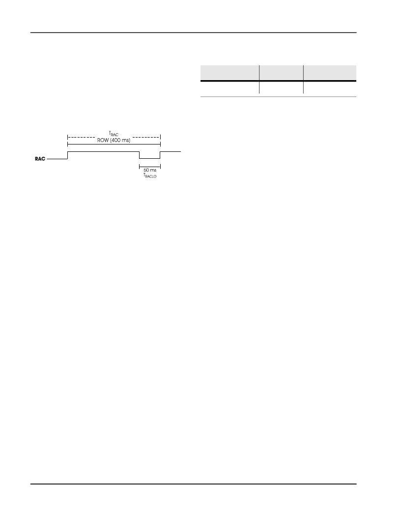
ROW ADDRESS CLOCK (RAC)
This is an open drain output pin that provides a sig-
nal with a 400 ms period at the 4 KHz sampling fre-
quency. (This represents a single row of memory
and there are 2400 rows of memory in the ISD Mi-
croTAD-16M devices.) This signal stays HIGH for 350
ms and stays LOW for 50 ms when it reaches the
end of a row.
The RAC pin stays HIGH for 218.76
μ
sec and stays
LOW for 31.26
μ
sec in Message Cueing mode
(see page 5 for a more detailed description of
Message Cueing). Refer to the AC Parameters ta-
ble for RAC timing information on other sample
rate products.
When a record command is first initiated, the RAC
pin remains HIGH for an extra T
RACLO
period. This is
due to the need to load sample and hold circuits
internal to the device. This pin can be used for
message management techniques.
EXTERNAL CLOCK INPUT (XCLK)
The external clock input for the ISD MicroTAD-16M
product has an internal pull-down device. These
products are configured at the factory with an in-
ternal sampling clock frequency centered to ± 1
percent of specification. The frequency is then
maintained to a variation over the entire com-
mercial temperature and operating voltage
ranges as defined by the minimum/maximum
limits in the applicable AC Parameters table. The
internal clock has a tolerance, overthe extended
temperature, industral temperature and voltage
ranges as defined by the minimum/maximum
limits in the applicable AC Parameters table. A
regulated power supply is recommended for in-
dustrial temperature range parts. If greater preci-
sion is required, the device can be clocked
through the XCLK pin in Table 1.
This recommended clock rate should not be var-
ied because the antialiasing and smoothing filters
are fixed. Thus, aliasing problems can occur if the
sample rate differs from the one recommended.
The duty cycle on the input clock is not critical, as
the clock is immediately divided by two internally.
If the X CLK is not used, this input should be
connected to ground.
AUTOMUTE FEATURE (AM CAP)
This pin is used in controlling the AutoMute feature.
The AutoMute feature attenuates the signal when
it drops below an internally set threshold. This helps
to eliminate noise (with 6 dB of attenuation) when
there is no signal (i.e., during periods of silence). A
1
μ
F capacitor to ground should be connected to
the AM CAP pin. This capacitor becomes a part of
an internal peak detector which senses the signal
amplitude (peak). This peak level is compared to
an internally set threshold to determine the Auto-
Mute trip point. For large signals the AutoMute at-
tenuation is set to 0 dB while 6 dB of attenuation
occurs for silence. The 1
μ
F capacitor also affects
the rate at which the AutoMute feature changes
with the signal amplitude (or the attack time). The
Automute feature can be disabled by connecting
the AM CAP pin to V
CCA
.
Table 1:
External Clock Input Clocking
Table
Part Number
Sample Rate
Required Clock
ISD MicroTAD-16M
4.0 KHz
512 KHz
相關PDF資料 |
PDF描述 |
|---|---|
| ISDNRNYNG | Optoelectronic |
| ISG4042-T | 5V CATV MODEM RF TUNER AND TRANSMITTER |
| ISG4042EU-T | 5V CATV MODEM RF TUNER AND TRANSMITTER |
| ISG52124-L | 5 TO 210 MHz SILICON CATV 24 dB LOW POWER HYBRID AMPLIFIER |
| ISG56518 | 5 TO 65 MHz SILICON CATV 18 dB HYBRID AMPLIFIER |
相關代理商/技術參數 |
參數描述 |
|---|---|
| ISDN | 制造商:TI 制造商全稱:Texas Instruments 功能描述:ISDN Basic Rate Interface Software for the HPC16400E High Performance Data Communications Microcontroller |
| ISDNRNYNG | 制造商:未知廠家 制造商全稱:未知廠家 功能描述:Optoelectronic |
| ISD-NU-LINK | 制造商:Nuvoton Technology Corp 功能描述:USB DONGLE A PORTABILITY PROGR 制造商:Nuvoton Technology 功能描述:USB DONGLE A PORTABILITY PROGR |
| ISD-PRO | 制造商:Silicon Laboratories Inc 功能描述:EMBER DESKTOP PROFESSIONAL EDITION (1 SEAT) - Boxed Product (Development Kits) 制造商:Silicon Laboratories Inc 功能描述:EMBER DESKTOP PROFESSIONAL 1SEAT |
| ISD-SR3000 | 制造商:未知廠家 制造商全稱:未知廠家 功能描述: |
發布緊急采購,3分鐘左右您將得到回復。