- 您現在的位置:買賣IC網 > PDF目錄361014 > IXPD610 Industrial Control IC PDF資料下載
參數資料
| 型號: | IXPD610 |
| 英文描述: | Industrial Control IC |
| 中文描述: | 工業控制IC |
| 文件頁數: | 7/8頁 |
| 文件大小: | 182K |
| 代理商: | IXPD610 |
2001 IXYS/DEI All rights reserved
IXDP 610
7
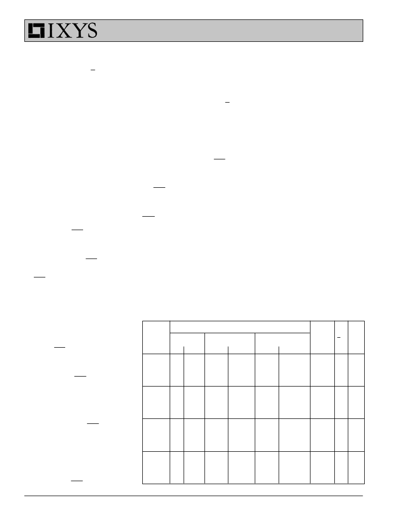
IXDP610's Control latch. The "%"
columns express the dead-time as a
percent of the PWM cycle time.
If a zero is written to the 7/8 bit the
IXDP610 is programmed for 7-bit
resolution, writing a one programs the
IXDP610 for 8-bit resolution. If a one is
written to the Divide bit, the external
clock (CLK) is divided by two before
being presented to the Pulse Width
counter; a zero in the Divide bit passes
CLK directly to the Pulse Width
Counter with no division of the
frequency. For a given CLK frequency
one can select three different PWM
frequencies: CLK/128, CLK/256, and
CLK/512. (CLK/256 can be selected for
either 7-bit or 8-bit resolution.
Software Considerations
Initialization and the Lock Bit
After power-up, the IXDP610 should
be reset via the RST input. Doing so
will guarantee the initial state of the
DPWM and effectively write a
01000111 binary to the Control latch.
Thus, after asserting RST, the
IXDP610 is set to the following state:
G
Stop is asserted, disabling OUT1
and OUT2
G
8-bit resolution is selected
G
CLK is divided by one (not divided
by two)
G
Lock bit is “UNLOCKED”
G
Dead-time Counter is set for
maximum dead-time.
Asserting RST is the only means by
which the
Lock bit can be “unlocked".
The lock bit must be cleared in order
to write to all other bits in the Control
latch, except the Stop bit.
The IXDP610 does not undergo an
internal reset on power-up; therefore,
it is recommended that the system
reset be connected to the DPWM, as
in Fig. 5. If one wishes to allow soft-
ware control over the RST input, they
should “OR” the system reset and an
I/O bit together, so the DPWM has a
known state following system reset.
Before initializing the Control latch,
one should first write a valid number
to the Pulse Width latch (i.e., a num-
ber that results in 0 V applied to the
load). Asserting RST clears the Pulse
Width latch.
During a write to the Control latch, all
bits can be modified simultaneously,
including the Lock bit. Thus, only one
write is necessary to set the dead-
time:
1) assert the Lock bit; 2) choose
the Divide bit state; 3) choose the
resolution. In most applications it is
not necessary to change the dead-
time bit, the Divide bit, or the 7/8 bit
“on the fly”. Therefore, it is recom-
mended that the Lock bit be asserted
during initialization of the Control
latch. Setting the Lock bit guarantees
that a software runaway will not
modify the state of the dead-time bit,
thereby preventing an accidental
short of the bridge. If the RST input is
accessible to the software (via an I/O
bit, spare chip select, etc.), the
hardware associated with asserting
the RST input should be designed to
minimize the possibility of resetting
the IXDP610 in the event of a soft-
ware runaway, since asserting the
RST input clears the Lock bit, allo-
wing modification of the DPWM's
Control latch.
Software Overflow Protection
In many applications, the Pulse
Width number written by the micro-
processor to the IXDP610’s Pulse
Width latch is the result of closed-
loop numeric calculations. Depending
on the algorithm used, the calculated
PWM number may be susceptible to
overflow, i.e. the calculated PWM
PWM
Fre-
quency
kHz
Dead-time Options
Min.
%
Step
Max.
CLK
MHz
7/8
bit
DIV
bit
μ
s
%
μ
s
%
μ
s
300
200
100
100
0
0
0
0
0
0
0
0
1.56
1.56
0.78
1.56
0.052
0.078
0.078
0.156
10.9
10.9
5.5
10.9
0.363
0.547
0.547
1.094
38.4
25.6
25.6
12.8
0
0
1
0
0
0
0
0
50
50
50
50
0
0
0
0
0
0
0
0
0.39
0.78
0.78
1.56
0.078
0.156
0.156
0.312
2.7
5.5
5.5
10.9
0.547
1.094
1.094
2.188
25.6
12.8
12.8
6.4
1
1
0
0
1
0
1
0
20
20
20
20
0
0
0
0
0
0
0
0
0.39
0.78
0.78
1.56
0.195
0.391
0.391
0.781
2.7
5.5
5.5
10.9
1.367
2.734
2.734
5.469
10.24
5.12
5.12
2.56
1
1
0
0
1
0
1
0
5
5
5
5
0
0
0
0
0
0
0
0
0.39
0.78
0.78
1.56
0.781
1.562
1.562
3.125
2.7
5.5
5.5
10.9
5.469
10.94
10.94
21.88
2.56
1.28
1.28
0.64
1
1
0
0
1
0
1
0
Table 4. Sample PWM Frequency and Dead-time Options
number could be larger than the
available 8-bits (or 7-bits) provided in
the Pulse Width latch. If this is the
case, it is important that the software
checks for overflow conditions before
writing a number to the Pulse Width
latch. Following is an example
assuming 8-bit resolution:
if (PWM__num < 0), check for
underflow, PWM__num = 0, set to
minimum limit
else if (PWM__num > 255), check for
overflow, PWM__num = 255; set to
maximum limit
Effect of Dead-time on Duty Cycle
The IXDP610 has been designed to
generate PWM signals that range
from 0 % to 100 %, inclusive. When
zero dead-time has been selected
(by writing 000 to the dead-time bits)
the duty cycle of a PWM cycle can be
determined by using the formulae
shown on page 32/33. Fig. 6 illustra-
tes the effect that a nonzero dead-
time has on the PWM waveform.
The dead-time feature built into the
IXDP610 guarantees that both OUT1
and OUT2 remain off for the duration
of the dead-time period. A dead-time
period occurs each time either OUT1
or OUT2 turns off; the dead-time
period overlaps the on-time of an
output (see Fig. 6c). Thus, if the
desired duty cycle is such that the
相關PDF資料 |
PDF描述 |
|---|---|
| IXR100 | IXR100 - DISCONTINUED PRODUCT. No longer recommended for new design. |
| IXSA12N60AU1 | TRANSISTOR | IGBT | N-CHAN | 600V V(BR)CES | 24A I(C) | TO-263AA |
| IXSE502PI | Servo Encoder |
| IXSE503PC | Servo Encoder |
| IXSE503PI | Servo Encoder |
相關代理商/技術參數 |
參數描述 |
|---|---|
| IXPN4004AR | 制造商:UNBRANDED 功能描述:CHARGER, NICAD, CHARGER UPGRADE KIT |
| IX-POLE-KIT | 制造商:PolyPhaser 功能描述:INTERCONNECT KIT |
| IXR100 | 制造商:BB 制造商全稱:BB 功能描述:Isolated, Self-Powered, Temperature Sensor Conditioning 4-20mA TWO-WIRE TRANSMITTER |
| IXRB5-506MINIPACK2 | 功能描述:IGBT 模塊 MiniPack 2 RoHS:否 制造商:Infineon Technologies 產品:IGBT Silicon Modules 配置:Dual 集電極—發射極最大電壓 VCEO:600 V 集電極—射極飽和電壓:1.95 V 在25 C的連續集電極電流:230 A 柵極—射極漏泄電流:400 nA 功率耗散:445 W 最大工作溫度:+ 125 C 封裝 / 箱體:34MM 封裝: |
| IXRFD630 | 制造商:IXYS Corporation 功能描述:DRIVER MOSFET 30A DE275 制造商:IXYS Corporation 功能描述:DRIVER, MOSFET, 30A, DE275 |
發布緊急采購,3分鐘左右您將得到回復。