- 您現(xiàn)在的位置:買賣IC網(wǎng) > PDF目錄30720 > LA7138M SPECIALTY CONSUMER CIRCUIT, PDSO24 PDF資料下載
參數(shù)資料
| 型號(hào): | LA7138M |
| 元件分類: | 消費(fèi)家電 |
| 英文描述: | SPECIALTY CONSUMER CIRCUIT, PDSO24 |
| 封裝: | 0.300 INCH, MFP-24 |
| 文件頁數(shù): | 9/13頁 |
| 文件大小: | 320K |
| 代理商: | LA7138M |
LA7138M
No.A0220-5/16
Design Guarantee Items at Ta = 25
°C
Ratings
Parameter
Symbol
Conditions
min
typ
max
Unit
Except for Y/C-MIX (VCCA = 9.0 to 13.0V, VCCB = 7.5 to 8.5V)
Channel crosstalk
CT
The signal which becomes 1Vp-p at f = 4MHz and with the output in
C connection is entered in other channels. Measure the magnitude
of monitor channel output pins at 4MHz and specify the ratings as a
ratio relative to the magnitude of output pin of other channels at
4MHz.
-65
-60
dB
Video S/N ratio
SN
Enter the Y signal with 100% white and apply 3.3V to pin 11.
Measure S/N of the output signal.
* Refer to Note 1.
-80
-78
dB
Differential gain
DG
Enter the 1Vp-p standard stair step signal (color) to obtain pin 11 =
OPEN. Measure the differential gain of the output signal, with the
output pin part shown in the measuring circuit diagram inserted.
0.5
2
%
Differential phase
DP
Enter the 1Vp-p standard stair step signal (color) to obtain pin 11 =
OPEN. Measure the differential phase of the output signal, with the
output pin part shown in the measuring circuit diagram inserted.
-1
0
1
dB
For Y/C-MIX (VCCB = 7.5 to 8.5V)
Channel crosstalk
CT
The signal which becomes 1Vp-p at f = 4MHz and with the output in
C connection is entered in other channels. Measure the magnitude
of monitor channel output pins at 4MHz and specify the ratings as a
ratio relative to the magnitude of output pin of other channels at
4MHz.
-65
-60
dB
Video S/N ratio
SN
Enter the Y signal with 100% white and add pin 11 = 3.3V. Measure
S/N of the output signal.
* Refer to Note 1.
-74
-72
dB
Differential gain
DG
Enter the 761mVp-p standard stair step signal (color) to obtain pin
11 = 3.3V. Measure the differential gain of the output signal, with the
output pin part shown in the measuring circuit diagram inserted.
4
5.5
%
Differential phase
DP
Enter the 761mVp-p standard stair step signal (color) to obtain pin
11 = 3.3V. Measure the differential phase of the output signal, with
the output pin part shown in the measuring circuit diagram inserted.
-1
0.5
1.5
dB
* Note 1) Since the noise in IC is dependent on the stability of regulator, it is recommended to connect a 470
F capacitor when the S/N ratio of –80dB is to be
secured for controls other than Y/C-MIX. To secure the S/N ratio of -74dB for Y/C-MIX, set the supply voltage to 8V (VCCB) and apply 8V also to this
pin. (See the test circuit B.)
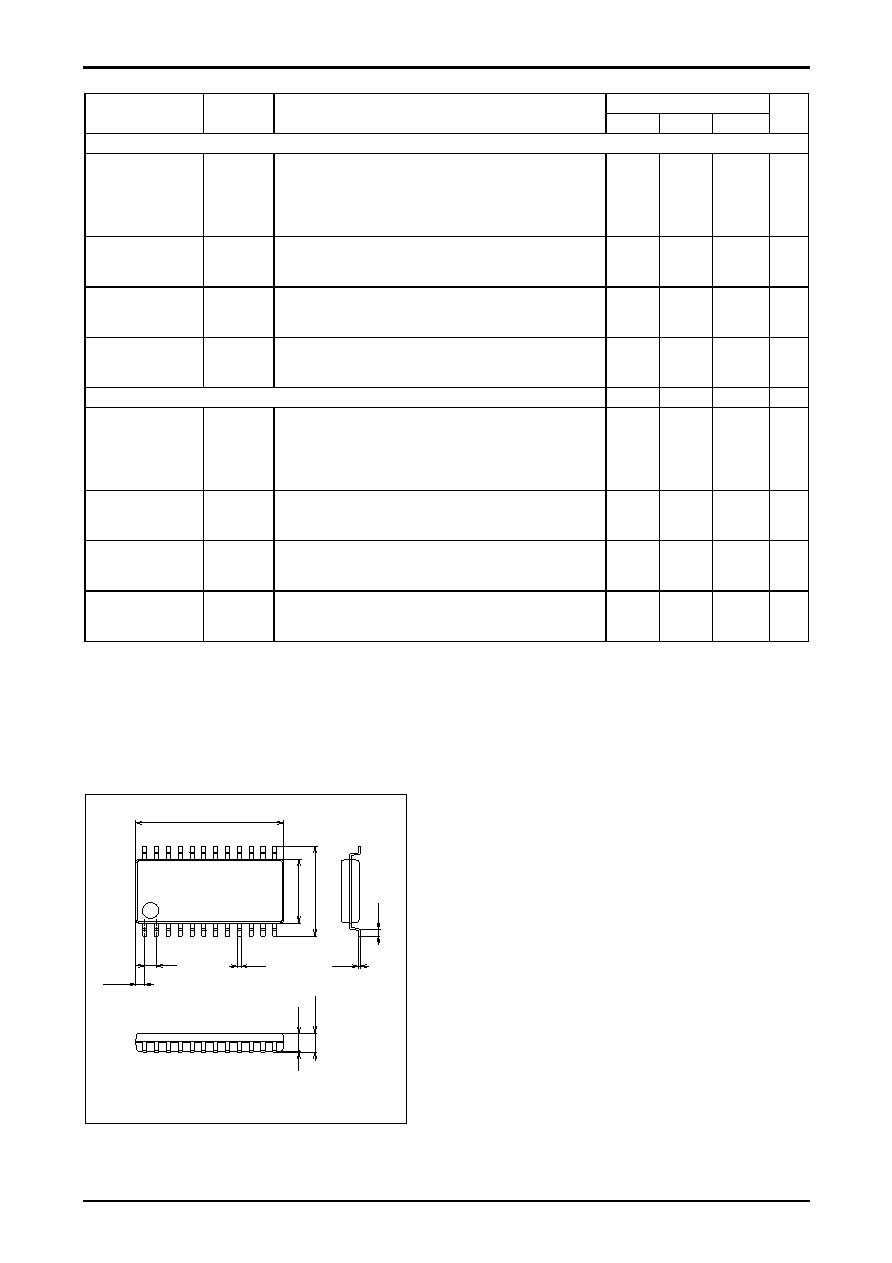
Package Dimensions
unit : mm
3112B
1
12
13
24
12.5
0.63
7.6
5.4
0.15
1.0
0.35
(0.75)
1.7max
0.1
(1
.5
)
SANYO : MFP24S(300mil)
相關(guān)PDF資料 |
PDF描述 |
|---|---|
| LA71521M | SPECIALTY CONSUMER CIRCUIT, PQFP80 |
| LA71578HM | SPECIALTY CONSUMER CIRCUIT, PQFP100 |
| LA71582M | SPECIALTY CONSUMER CIRCUIT, PQFP100 |
| LA71582M | SPECIALTY CONSUMER CIRCUIT, PQFP100 |
| LA71584M | FM, AUDIO/VIDEO DEMODULATOR, PQFP100 |
相關(guān)代理商/技術(shù)參數(shù) |
參數(shù)描述 |
|---|---|
| LA7140 | 制造商:未知廠家 制造商全稱:未知廠家 功能描述: |
| LA7150 | 制造商:SANYO 制造商全稱:Sanyo Semicon Device 功能描述:Audio/Video Switch for PAL System VCR |
| LA7151 | 制造商:SANYO 制造商全稱:Sanyo Semicon Device 功能描述:Audio/Video Switch for VCR Video Camera Use |
| LA7151M | 制造商:SANYO 制造商全稱:Sanyo Semicon Device 功能描述:Audio/Video Switch for VCR Video Camera Use |
| LA7152 | 制造商:SANYO 制造商全稱:Sanyo Semicon Device 功能描述:VCR Electronic Switch |
發(fā)布緊急采購,3分鐘左右您將得到回復(fù)。